background image

ELE-8 

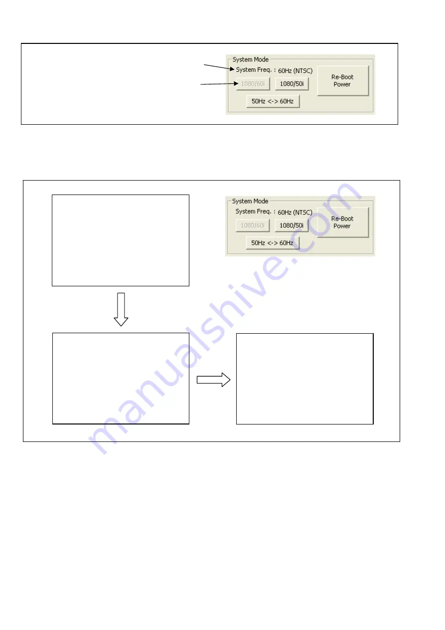
< Setting of System Mode >


System Mode can be set on the Adjustment Tool screen. 

 
System Mode is set to 1080/60i as shown in the following screen. The setting procedure of System Mode is as 
follows (Ex.: When setting it to 1080/50i.). 
1. Click the 

“1080/50i”

 or 

“50Hz<->60Hz”

 button. And click the 

“Re-Boot Power”

 button after the message 

“TURN POWER OFF”

 is displayed on the LCD panel. The power of camera recorder is automatically OFF and 

ON. 


The System frequency is displayed. 

It is set to this System Mode. 

SYSTEM MODE 

 
COMPLETED !


TURN POWER OFF 

SYSTEM MODE 

 
PROCESSING . . .


Summary of Contents for AG-HPX250P

Page 1: ...Procedure ELE 7 2 1 Adjustment Tool screen ELE 7 2 1 1 Zoom center Adjustment ELE 9 2 1 2 Hall Amp Iris PWM OIS Hall Amp Adjustment ELE 9 2 1 3 Zoom tracking and De focus Adjustment ELE 10 2 1 4 White Balance Adjustment ELE 13 2 1 5 Blemish Compensation Adjustment ELE 14 2 1 6 White Shading Adjustment ELE 15 2 1 7 ND FILTER Compensation Adjustment ELE 16 2 1 8 Video Output Level Adjustment ELE 18 ...

Page 2: ...era recorder is set to COM mode Setting method of COM mode 2 1 Turn the power on and confirm that the camera recorder is set to CAMERA mode 2 2 The COM mode is set by hold down the PLAY Tilt the operation lever in the direction button EXIT button and RESET button at the same time for three seconds or more The character of COM blinks to the LCD screen when the COM mode is set NOTE To cancel the COM...

Page 3: ... window check Install from a list of specific location Advanced and click Next button 2 The following screen is displayed Put the check in Include this location in the search and click Browse button 3 The Browse For Folder screen is displayed Select the folder that the driver entered Next click Next button on Found New Hardware Wizard screen ...

Page 4: ...g message window may appear after a while clicking Next button on the Found New Hardware Wizard screen Click Continue Anyway button 5 When the installation is completed the following screen is displayed Click Finish button ...

Page 5: ...ation between the PC and the Camera Recorder has been succeeded blue is displayed to the status lamp 6 The communication status between the PC and the camera recorder can be confirmed with the status lamp as following color Not Connected black Connected blue Reading green Writing red NOTE When the OK button is clicked on the Selection screen Detection of not initialized P C Board might be executed...

Page 6: ...2 Collimator Adaptor AUTO Adj White Balance Adjustment White Chart Halogen lamp Color Pyrometer Lux Meter AUTO Adj Blemish Compensation Adjustment White Chart Halogen lamp Color Pyrometer Lux Meter AUTO Adj White Shading Adjustment White Chart Halogen lamp Color Pyrometer Lux Meter AUTO Adj ND FILTER Compensation Adjustment White Chart Halogen lamp Color Pyrometer Meter AUTO Adj Video Output Level...

Page 7: ... X X X ND FILTER Compensation Adjustment X X X Video Output Level Adjustment X X Int Frequency Adjustment X X X Adjustment Confirmation Required The method of data backup EEPROM has been described to the item 8 Save and write EEPROM data of service information SECTION 1 ADJISTMENT ITEM Savings IC of adjustment data Zoom center Adjustment CAM EEPROM Hall Amp Iris PWM OIS Hall Amp Adjustment CAM EEP...

Page 8: ...reen 1 Select Adjustment Tool in Tools W menu Adjustment Tool screen will appear on screen 2 Adjustment Procedure Adjustment completion message is displayed in this STATUS column 2 1 Adjustment Tool screen Shutter Button ND Button These buttons are used at the time of Blemish Compensation and White Shading adjustment ...

Page 9: ...stem Mode is as follows Ex When setting it to 1080 50i 1 Click the 1080 50i or 50Hz 60Hz button And click the Re Boot Power button after the message TURN POWER OFF is displayed on the LCD panel The power of camera recorder is automatically OFF and ON The System frequency is displayed It is set to this System Mode SYSTEM MODE COMPLETED TURN POWER OFF SYSTEM MODE PROCESSING ...

Page 10: ...hen the adjustment is completed the following message screen is displayed Turn the power of camera recorder to OFF and clicking OK button PC EVR software closes compulsorily 1 Select CAM C section after start up the PC EVR software and click OK button 2 Select Adjustment Tool in Tools W menu Adjustment Tool screen will appear on screen 3 Clicking the Execute button the adjustment is executed autom...

Page 11: ... position of lens unit and collimator so that the center of chart is always located at the center of monitor when moved between T and W 9 Select CAM C section after start up the PC EVR software and click OK button 10 Select Adjustment Tool in Tools W menu Adjustment Tool screen will appear on screen 11 Clicking the Start button as follows on the Adjustment Tool screen 12 PC EVR software checks the...

Page 12: ...djustment is completed the message Tracking Adjustment Completed is displayed in the STATUS column on the Adjustment Tool screen and the following message screen is displayed Clicking OK button power is turned OFF and ON automatically and PC EVR software closes compulsorily Completion message ...

Page 13: ...ter 3 Tighten the 4 hex screws A and install the Attachment ring to adapter as shown in figure 4 Tighten the 2 hex screws B as shown in figure and the Collimator RFKZ0422 is fixed to the Collimator Adapter 5 Set the Collimator RFKZ0422 with the Collimator Adapter to the front of Lens as shown in figure Attachment ring Adapter Hex Screw A X 4 Hex Screw B X 2 Collimator Space Adapter Attachment ring...

Page 14: ...ring 11 Clicking the Execute button for P A P Type2 the white balance adjustment is executed automatically 12 When the adjustment is completed the message White Balance Completed is displayed in the STATUS column on the Adjustment Tool screen 13 Confirm that the vector dot is located at the zero point in the WFM vector scope 14 Confirm that there is no colored on Monitor TV 15 Open the OPTION MENU...

Page 15: ...lick the Start button for Black Blemish AWB is executed automatically 10 Confirm that the white level of signal is about 65 to 75 If it is not adjust ND or SHUTTER so that the white level of signal is become about 65 to 75 with Shutter ND Button on the Adjustment Tool screen 11 Clicking the Execute button the Blemish Compensation adjustment Black Blemish Compensation is executed automatically 12 W...

Page 16: ...en will appear on screen 7 Initial setting is required for two lens position before the adjustment 8 Click the Start button for Pos 1 9 Confirm that the white level of signal is about 70 to 90 If it is not adjust SHUTTER so that the white level of signal is become about 70 to 90 with Shutter Button on the Adjustment Tool screen 10 Click the Set button for Pos 1 11 Click the Start button for Pos 2 ...

Page 17: ...ng the Execute button for ND Filter1 the ND Filter1 ND 1 4 adjustment is executed automatically 14 When the adjustment is completed the message ND Adjustment END is displayed in the STATUS column on the Adjustment Tool screen 15 Confirm that the vector dot is located at the zero point in the WFM vector scope 16 Confirm that there is no colored on Monitor TV 17 Click the Set button for ND Filter1 t...

Page 18: ...column on the Adjustment Tool screen 29 Confirm that the vector dot is located at the zero point in the WFM vector scope 30 Confirm that there is no colored on Monitor TV 31 Click the Set button for ND Filter3 to end of ND Filter3 adjustment mode The adjusted value is saved in EEPROM Clicking the Set button the adjusted value is saved in EEPROM Start button Adjustment value R ch Upper Lower B ch U...

Page 19: ...system frequency to 50Hz by clicking 50Hz 60Hz button on the Adjustment Tool screen Click the 50Hz 60Hz button And click the Re Boot Power button after the message TURN POWER OFF is displayed on the LCD panel The power of camera recorder is automatically OFF and ON 9 Adjust Luminance level Y by clicking the adjustment button for Y so that it is within specification 10 Adjust Burst level C by click...

Page 20: ...of an adjustment value finally 12 Click the Set button for X tal Oscillator Freq to end of internal frequency adjustment mode 13 Change the system frequency to 50Hz by clicking 50Hz 60Hz button on the Adjustment Tool screen Click the 50Hz 60Hz button And click the Re Boot Power button after the message TURN POWER OFF is displayed on the LCD panel The power of camera recorder is automatically OFF a...

Reviews: