background image

Menu

99


OTHER FUNCTIONS screen (continued)

Item

Display 

mode

Description of settings

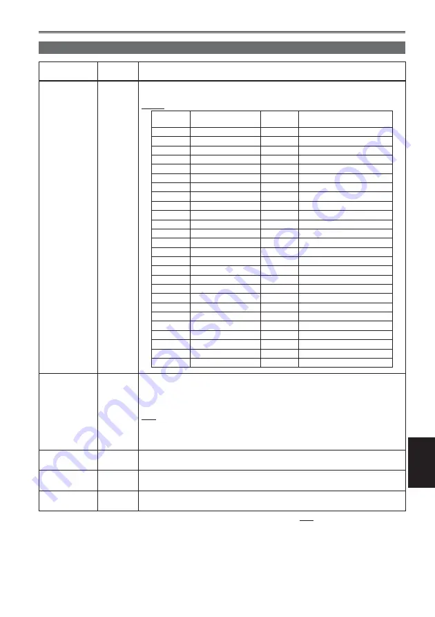
TIME ZONE

(Camera)
(PB)

Adds to or deducts from GMT the time value of -12:00 to +13:00 in 30-minute 
steps. (Refer to the table below.)

+00:00

Time 
difference

Area

Time 
difference

Area

+ 00:00

Greenwich

– 00:30

– 01:00

Azores Islands

– 01:30

– 02:00

Mid-Atlantic

– 02:30

– 03:00

Buenos Aires

– 03:30

Newfoundland Island

– 04:00

Halifax

– 04:30

– 05:00

New York

– 05:30

– 06:00

Chicago

– 06:30

– 07:00

Denver

– 07:30

– 08:00

Los Angeles

– 08:30

– 09:00

Alaska

– 09:30

Marquesas Islands

– 10:00

Hawaii

– 10:30

– 11:00

Midway Island

– 11:30

– 12:00

Kwajalein

+ 12:30

+ 13:00

+ 11:30

Norfolk Island

+ 12:00

New Zealand

+ 10:30

Lord Howe Island

+ 11:00

Solomon Islands

+ 09:30

Darwin

+ 10:00

Guam

+ 08:30

+ 09:00

Tokyo

+ 07:30

+ 08:00

Beijing

+ 06:30

Yangon

+ 07:00

Bangkok

+ 05:30

Mumbai

+ 06:00

Dacca

+ 04:30

Kabul

+ 05:00

Islamabad

+ 03:30

Tehran

+ 04:00

Abu Dhabi

+ 02:30

+ 03:00

Moscow

+ 01:30

+ 02:00

Eastern Europe

+ 00:30

+ 01:00

Central Europe

POWER SAVE

(Camera)

Selects the power-saving mode when either the Operation lever, or the MENU, 
AUDIO MON/ADV, USER, START/STOP, or STAND BY button, has not been 
operated for about 5 minutes while a memory card is inserted in the CAM mode.

ON:


The camera-recorder’s power is set to OFF.

OFF:


The camera-recorder’s power is not set to OFF.

Even when this setting is ON, the power will not turn OFF when an SD Memory 
Card is not inserted, when the camera-recorder is in PB mode or PC mode, or 
when the AC adapter is connected.

SYSTEM INFO

(Camera)
(PB)

Displays the version of the system in this camera.

MENU INIT

(Camera)

Returns the menu settings (scene file, user file) to the factory settings.

TIME ZONE setting will not return to the factory setting.

OPERATION 
TIME

(Camera)
(PB)

Displays the power-on time (a 5-digit figure).

        indicates the factory setting.

Summary of Contents for AG-HMC152EN

Page 1: ...Printed in Japan VQT1V36 Operating Instructions Memory Card Camera Recorder Model No AG HMC152EN Before operating this product please read the instructions carefully and save this manual for future use ENGLISH This product is eligible for the AVCCAM 3 Year Warranty Repair Program For details see page 5 D ...

Page 2: ... explosion or fire if battery is mistreated For Battery Pack Replace only with same or specified type Do not disassemble or dispose of in fire Do not store in temperatures over 60 C 140 F Do not leave the battery in an automobile exposed to direct sunlight for a long period of time with doors and windows closed Use specified charger For Battery of Remote Controller Replace battery with part No CR2...

Page 3: ...right owners and be contrary to copyright laws Operating precaution Operation near any appliance which generates strong magnetic fields may give rise to noise in the video and audio signals If this should be the case deal with the situation by for instance moving the source of the magnetic fields away from the unit before operation ...

Page 4: ...ase be advised that we are not liable for any accident or failure occurring as a result of use of a counterfeit battery pack To ensure that safe products are used we would recommend that a genuine Panasonic battery pack is used Be aware that many batteries sold at extremely cheap prices or in situations where it is difficult to verify the actual products before purchase have proven to be counterfe...

Page 5: ...tration and the extended warranty http panasonic biz sav pass_e Free 3 years of Warranty Repairs Customers who register as users on the website will receive an extended warranty repair valid for up to three years AVCCAM 3 Year Warranty Repair Program 1 Thank you for purchasing this Panasonic AVCCAM device Register as a user for this device to receive a special service warranty up to three years of...

Page 6: ...SD Memory Cards 33 Repairing SD Memory Cards 33 Using the zoom function 34 Digital zoom function 34 Shooting in progressive mode 35 Shooting in manual mode 36 Switching to manual mode 36 Manual focusing 36 Using focus assist 37 Iris adjustments 37 Adjusting the gain 38 Light intensity adjustments 38 Adjusting the white balance 38 Shooting techniques for different targets 41 Low angle recording 41 ...

Page 7: ...ernal microphone 71 Computer non linear editing file transfer 72 Video deck Dubbing 72 TV Monitor 73 Nonlinear editing PC mode 75 Displays Screen displays 76 Regular displays 76 Main warning displays 79 Setting the DISPLAY items 81 Menu Using the setup menus 82 Using the menus 82 Initializing the menu settings 83 Setup menu structure 84 Camera mode menu 84 Playback mode menu 85 Setup menu list 86 ...

Page 8: ...SD SDHC Memory Card 32 LOCK Images can be recorded in HD high definition Please see page 109 for details on the handling of recorded data A set number of user files can be recorded to and read from the SD Memory Card Page 52 Computer Send data files to your computer for non linear editing etc 2 PC mode Page 75 USB2 0 Recording to and playback from SD SDHC Memory Cards Pages 30 59 1 32 LOCK SD SDHC...

Page 9: ...ge at the following website for the latest information not included in these operating instructions https eww pavc panasonic co jp pro av This product is compatible with SD Memory Cards formatted under the SD standard FAT12 and FAT16 formats and with SDHC Memory Cards formatted under the FAT32 format Only SDHC Memory Cards may be used for capacities of 4 GB or greater 4 GB or greater memory cards ...

Page 10: ...us writing of data between SD compatible devices and SD Memory Cards as designated by the SD standards When the use of an SD speed class 4 card is recommended for SD compatible products this indicates that stable recording operation can be achieved when using SD Memory Cards of class 4 and above Cautions for usage Do not allow dirt water or other substances to come into contact with the connector ...

Page 11: ...y Cards Respect copyrights Copyright laws forbid the use of video and audio material you have recorded for any purpose other than your own personal enjoyment Remember that restrictions apply to the shooting of certain material even if it is intended for private use Caution regarding laser beams The CCD may be damaged if it is subjected to light from a laser beam When using the camera recorder in l...

Page 12: ...these operating instructions are trademarks or registered trademarks of their respective companies This product is licensed under the AVC Patent Portfolio License for the personal and non commercial use of a consumer and no license is granted or shall be implied for any use other than the personal uses detailed below To encode video in compliance with the AVC standard AVC Video To decode AVC Video...

Page 13: ...non SDHC compatible equipment Ensure that all equipment is SDHC compatible when using card with other devices Page 10 Compatibility of recorded video Recorded video cannot be used with non AVCHD compatible equipment For details please see your product s operating instructions Recorded video cannot be played back on non compatible non AVCHD compatible equipment Playback may not always be possible o...

Page 14: ...der belt CD ROM The following accessories are attached to the unit Lens hood cap INPUT 1 2 terminal cover 2 1 For part numbers for the battery see Optional accessories 2 When using a USB connection cable optional or HDMI cable optional attach the ferrite cores at both ends of the cable Pages 72 73 Please consult a retailer when purchasing additional accessories Optional accessories XLR microphone ...

Page 15: ...om button Page 34 8 Handle START STOP button Page 41 9 Built in stereo microphone Page 48 10 White balance sensor Page 40 11 Remote control sensor Front Page 22 12 Tally lamp Front Page 23 13 INPUT 1 2 audio input switches Page 48 14 Viewfinder Page 24 15 SD Memory Card slot cover Page 30 16 SCENE FILE dial Page 50 17 STAND BY button Page 23 18 Mode button Pages 30 and 59 19 Tally lamp Rear Page 2...

Page 16: ...r adjustment dial Page 24 8 FOCUS switch Page 36 9 PUSH AUTO button Page 36 10 AWB button Page 38 11 IRIS dial Page 37 12 ND FILTER switch Page 38 13 IRIS button Page 37 14 GAIN switch Page 38 15 WHITE BAL switch Page 38 16 RING FOCUS IRIS selector switch Page 36 17 DISP MODE CHK button Page 42 18 AUTO MANUAL switch Pages 30 and 36 19 AUDIO control knobs CH1 CH2 Page 49 20 LCD monitor Page 25 21 O...

Page 17: ...us page 2 5 Tripod hole Page 11 6 AUDIO OUT CH1 CH2 terminals Pages 72 and 73 7 VIDEO OUT terminal Pages 72 and 73 8 INPUT 1 2 terminals XLR 3 pin Page 71 9 SD Memory Card slot Page 30 10 SD Memory Card access lamp Page 31 11 USB terminal Mini B Pages 72 and 75 12 HDMI OUT terminal Page 73 13 COMPONENT OUT terminal Page 73 14 CAM REMOTE jack FOCUS IRIS 3 5 mm mini jack You can connect a remote con...

Page 18: ...EARCH STILL ADV STILL ADV SEARCH 3 4 6 8 1 2 5 7 8 9 10 11 6 10 12 Remote control usable range Page 22 Recharging the battery Recharging The battery does not come ready charged when the camera is purchased Charge the battery before use It is recommended that you keep one extra battery as a spare 1 Connect the power cord to the AC adapter Disconnect the DC cord Battery cannot be charged if DC cord ...

Page 19: ...ly when using in high or low temperatures or when the battery has not been used for a long period of time To ensure that remaining battery capacity is displayed correctly use the battery completely from a fully charged state and charge the battery again Remaining battery capacity may still not be displayed correctly if the battery has been used for long periods in high or low temperatures or if th...

Page 20: ...t the DC cord to the AC adapter 2 Plug the AC power supply cord into the power outlet 3 Insert the DC cord s battery connector until it clicks into place DC cord s battery connector Removal 1 Set the POWER switch to OFF and check that the mode lamp is off 2 Remove the DC cord s battery connector while pressing the battery release button 3 Disconnect the AC power supply cord from the power outlet B...

Page 21: ...trap Attach the shoulder strap and use it as a precaution against dropping the camera 20 mm or more 20 mm or more Detaching and attaching the lens hood Detaching the lens hood Turn the lens hood counterclockwise to detach it Attaching the lens hood Rotate the lens hood clockwise until it clicks to fit into place Be sure to attach the lens hood cap to protect the lens when not in use Lens hood cap ...

Page 22: ...ry battery is used Remote control sensor Rear Remote control sensor Front The remote control is intended for indoor operation Outdoors or under strong light the unit may not operate properly even within the usable ranges Turn on off the camera While pressing the lock release button move the POWER switch to ON or OFF Turn on the camera The mode lamp CAM lights red CAMERA mode and the camera is now ...

Page 23: ...ry is low Battery has been removed When the STAND BY button is pressed in the standby mode the mode lamp CAM will flash more quickly and the standby mode will be extended by 30 minutes It also flashes more quickly five minutes before the standby mode is canceled During standby mode the camera will still consume approximately 60 of the power it would during paused recording meaning that available r...

Page 24: ...st to see You can move the viewfinder out to about 90 perpendicular to the camera 3 Adjust the diopter adjustment dial so that you can see the characters on the viewfinder screen clearly Diopter adjustment dial Eye piece Do not allow the eyepiece of the viewfinder to remain in direct contact with sunlight or other strong light sources Internal components may be damaged and fire may be caused if li...

Page 25: ...cord no card etc Recording in progress during transition to the recording pause mode Recording paused recording standby Warning display Emphasizing outlines Emphasizing the outlines of the images you see in the viewfinder or on the LCD makes it easier to focus Emphasizing the outlines does not effect the images you shoot 1 In CAM mode press EVF DTL button EVF DTL ON appears on the screen for about...

Page 26: ...DISPLAY SETUP screen LCD monitor adjustments Set YES under LCD SET on the setting menu DISPLAY SETUP screen 4 Select the desired item by tilting the Operation lever in the directions and push the Operation lever 5 Adjust the selected item by tilting the Operation lever in the directions 6 Press MENU button to exit the menus The viewfinder display can be in color or black and white See the setup me...

Page 27: ...nd video images can be verified by reversing the images displayed on the LCD monitor horizontally or vertically The recorded images will not be affected if the images are reversed on the screen 1 Select LCD REV in the LCD item on the settings menu SW MODE screen LCD REV can be assigned with the LCD button 2 Press the LCD button Press the button to switch between normal display and reverse display ...

Page 28: ...he Operation lever or tilt lever in direction 4 Pushing the Operation lever twice brings up the setting screen Tilt the Operation lever in the directions to set the time difference from Greenwich Mean Time and push the Operation lever again Factory default setting is 00 00 Setting the calendar 5 Tilt the Operation lever in the direction and select YES in the CLOCK SET item on the settings menu OTH...

Page 29: ...ation screen and push the Operation lever again The clock can vary in accuracy so check that the time is correct before shooting When using the camera overseas do not set the CLOCK SET option to the local time but instead enter the time difference from Greenwich mean time according to TIME ZONE ...

Page 30: ...e button 1 3 PB Mode button Mode lamp Preparing for recording 1 Set the camera s power switch to OFF Page 22 Check that the mode lamp is off 2 Tilt the viewfinder upwards and open the SD Memory Card slot cover by sliding it to the left 3 Fully insert an SD Memory Card into the card slot 4 Close the SD Memory Card slot cover Ensure that the cover firmly clicks into place 2 Insert the connector part...

Page 31: ...R switch has been set to ON Checking photos taken REC CHECK Press the REC CHECK button while recording is paused The last two seconds of video and audio will be played and the camera will then return to the recording pause mode Only the POWER and START STOP buttons are operable during REC CHECK The REC CHECK images are also recorded when a device is connected to the camera and backup images have b...

Page 32: ...rox 360 min 32 GB Approx 180 min Approx 240 min Approx 320 min Approx 720 min 1 Use an SD memory class of SD speed class 4 or above when recording on PH mode or HA mode Recording cannot be completed on SD Memory Cards of lower speed classes 2 Use an SD memory class of SD speed class 2 or above when recording in HG mode or HE mode Recording cannot be completed on SD Memory Cards of lower speed clas...

Page 33: ...d the next time the power is switched on in order to allow errors to be repaired Select YES to begin repairing When repairing is complete REPAIR FINISHED will be displayed and the camera will switch to the recording paused screen Select NO to switch directly to the recording paused screen without repairing Memory cards cannot be repaired with the camera if NO is selected but can still be repaired ...

Page 34: ...E FILE screen Page 87 is set to OFF The digital zoom setting cannot be adjusted during recording The shutter speed cannot be set to 1 12 or 1 25 while the digital zoom function is in use Moreover the digital zoom function cannot be used while the shutter speed is set to 1 12 or 1 25 Using the zoom function This camera has a 13 x optical zoom function Zoom with the zoom button or the zoom ring Zoom...

Page 35: ...frames a second in the progressive mode For output and recording the 25 frame per second signal is converted to 50 field per second interlace This mode gives you high quality images AoAeBoBeCoCeDoDeEoEeFoFeGoGeHoHe Io Ie Jo Je A B C D E F G H I J 25 P 50 i Note the following when shooting in progressive mode You cannot have a gain of 18 dB Set the shutter speed to 1 50 OFF for best results ...

Page 36: ...utomatically moves back to M MANUAL after you move it to 3 The function allocated to the focus ring can be changed with the RING FOCUS IRIS switch FOCUS Adjust the focus IRIS Adjust the iris aperture setting Temporarily switching to auto focus Even if you have switched FOCUS to M MANUAL the camera will focus automatically while you press down PUSH AUTO Auto focus may not work properly if there is ...

Page 37: ... wide angle W and F3 0 or OPEN when set to maximum telescopic T Using focus assist Pressing the FOCUS ASSIST button enlarges the center of the screen or displays a frequency distribution graph in the top right of the screen enabling the focus to be aligned more easily and therefore particularly useful when using manual focus The screen display that appears after pressing the FOCUS ASSIST button ca...

Page 38: ...d 1 12 has been set the gain is fixed at 0 dB regardless of the GAIN switch setting Page 46 Light intensity adjustments Use the ND FILTER switch to change the ND Filter used filter to change light intensity OFF ND filter is not used 1 4 Cuts light intensity by up to about 1 4 1 16 Cuts light intensity by up to about 1 16 1 64 Cuts light intensity by up to about 1 64 ND FILTER switch Adjusting the ...

Page 39: ...e cannot be adjusted if the ATW Auto Tracking White function is working If you have set ON under ATW on the setting menu AUTO SW screen ATW will be selected when auto mode has been established regardless of the WHITE BAL switch position Page 90 Make the necessary adjustments if one of the following error messages appears then try adjusting the white balance again Error messages Adjustments LOW LIG...

Page 40: ...nt before proceeding Message during adjustment ABB ACTIVE Message after adjustment ABB END Black balance can be adjusted by holding the AWB button down even when the ATW function is in use You cannot adjust the black balance while you are shooting Auto Tracking White ATW Using the ATW function enables the recording environment to be automatically analyzed and an optimum white balance to be constan...

Page 41: ...al recording and check what the message says To confirm screen display information on the viewfinder turn the LCD monitor to the normal shooting position Images will be inverted horizontally when outputting to an external device Zebra pattern Press the ZEBRA button in the CAM mode to show the zebra pattern or marker on the viewfinder and the LCD monitor so you can check the brightness of the subje...

Page 42: ...POWER switch to the OFF position or if the operating mode is changed Pressing the DISP MODE CHK button while the thumbnail screen is displayed in PB mode will display the properties of the selected clip Clips can be selected by moving the cursor with the Operation lever Shooting techniques for different targets continued PRE REC Record video and audio from three seconds before the time of the oper...

Page 43: ... buttons Use these buttons to change shooting settings quickly or add effects to the images you are shooting The following features are allocated to the buttons at the time of shipping USER1 WHITEFADE USER2 BACKLIGHT USER3 INDEX For details see the setup menus SW MODE screen USER1 to 3 Page 88 If you press a USER button to which one of the functions has been allocated and then turn off the power t...

Page 44: ...n the viewfinder This function cannot be used while the focus assist function is in operation Wave forms cannot be recorded While wave forms are displayed use the viewfinder as well since part of the recording screen will be hidden by the wave forms Adjusting the volume while shooting AUDIO MON ADV Adjusting the volume AUDIO MON ADV If you are monitoring the sound through headphones while shooting...

Page 45: ...e valid Time stamp function The date and time of recording can be recorded to video images Select ON in the TIME STAMP item on the settings menu RECORDING SETUP screen When the TIME STAMP function is ON the letter R will be displayed in front of the date and time display in the viewfinder and the LCD monitor The letter R display itself will not be recorded to the video The size and position of the...

Page 46: ...or use SHUTTER 1 50 The current shutter speed appears on the viewfinder and LCD monitor unless you have selected OFF in OTHER DISPLAY in the DISPLAY SETUP screen of the setup menus It is not displayed if you have set the shutter speed to normal OFF With artificial lighting and especially fluorescent lights and mercury vapor lamps the luminance changes in synchronization with the power line frequen...

Page 47: ...television or computer monitor to minimize the horizontal noise that appears when shooting such subjects If the SYNCRO SCAN item is displayed in grey it cannot be used with the current recording format This function will only operate for preset values for each recording format as listed below 50i 50P mode 1 50 25P mode 1 25 You can change the progressive mode in the setup menu with REC FORMAT in t...

Page 48: ...phone and audio equipment 1 Connect an external microphone or audio equipment to the INPUT 1 2 XLR 3 pin terminals Page 71 2 Use the INPUT 1 2 switches to switch the audio input LINE audio equipment is connected Input level is 0 dBu MIC an external microphone is connected Input level is 50 dBu You can change the input level to 60 dBu in the setup menus RECORDING SETUP screen MIC GAIN1 and MIC GAIN...

Page 49: ...camera is set approximately 8 dB higher than Panasonic broadcasting camera recorders AJ series products 4 Use the CH1 SELECT switch to select the input signal to be recorded to audio channel 1 INT L Audio from the built in microphone Lch is recorded to audio channel 1 INPUT 1 Audio from a device connected to INPUT 1 terminal is recorded to channel 1 INPUT 2 Audio from a device connected to INPUT 2...

Page 50: ...em on the RECORDING SETUP screen Page 91 F6 SCENE CINE D File suitable for shooting movie like scenes where the dynamic range is to be emphasized The recording format remains unchanged even when the scene file is changed It must be set using the REC FORMAT item on the RECORDING SETUP screen Page 91 Changing scene file settings The setting value of the scene file can be changed Also you can save th...

Page 51: ...9 _ If the RESET TC SET button is pressed when the filename has been set the characters are cleared 7 After you finish setting the filename push the Operation lever 8 Select YES on the confirmation screen Selecting YES will close the NAME EDIT screen and confirm all changes Once confirmed all changed names and values will be saved even if the power is switched off or the scene dial is moved ...

Page 52: ...e the protected status of the SD Memory Card If WRITE NG CANNOT ACCESS appears quit all other operations such as playback before proceeding You can save up to four scene file settings or other settings as files on an SD Memory Card and you can also load them from the card In the case of the scene files the current settings are automatically saved in the unit and the saved data is written on an SD ...

Page 53: ... and MODEL NAME equipment model name AG HMC150 SHOOT This indicates the SHOOTER name of the videographer and the PLACE NAME name of location LOCATION This indicates ALTITUDE LONGITUDE LATITUDE and SOURCE altitude longitude latitude information source SCENARIO 2 This indicates the PROGRAM NAME SCENE NO and TAKE NO NEWS 1 This indicates the REPORTER name of the reporter and PURPOSE purpose of data c...

Page 54: ...e loaded they are displayed as RECORD Select this to set whether to record the metadata to be loaded into the unit simultaneously on the SD Memory Card Select ON to record the metadata or OFF to cancel the recording and push the Operation lever The factory setting for this mode is OFF USER CLIP NAME The USER CLIP NAME recording method is selectable Please refer to the next column below CLIP COUNT ...

Page 55: ...r MASTER settings 2 Check that the MASTER camera is set to the CAM mode and set the EXT TC LINK item on the setting menu TC UB SETUP screen to MASTER OUTPUTTING LTC SIGNAL is displayed on the screen and the time code is output from the TC PRESET IN OUT terminal VIDEO OUT terminal Select the same REC FORMAT settings for both the MASTER and SLAVE cameras and set the TCG item on the TC UB SETUP scree...

Page 56: ...ized after recharging the internal battery requires changing Please consult the place of purchase Setting the time code In the setup menus TC UB SETUP screen set the following time code related items Page 92 TCG TC PRESET Charging the built in battery Setting the time code Specifying the time code TC PRESET Set TC PRESET so you can record a value of your choice as the initial setting for the time ...

Page 57: ...elect value You can reset the time code to zero by pressing RESET TC SET button BARS LCD ZEBRA OIS EVF DTL WFM CH1 SELECT CH2 SELECT INPUT 1 INPUT 2 SHUTTER COUNTER RESET TC SET AUDIO SPEED SELECT INT L INPUT1 INPUT2 INT R INPUT2 ON MIC POWER 48V OFF ON OFF Camera 5 Push the Operation lever when you have finished setting the time code 6 Tilt the Operation lever in the direction to move to YES and ...

Page 58: ...eration lever 4 Set the user information Tilt the Operation lever in the directions and select user information characters You can use numbers from 0 to 9 and letters from A to F Tilt in the direction to move to the next digit and tilt in the directions again to select character You can reset the user information to nothing by pressing RESET TC SET button BARS LCD ZEBRA OIS EVF DTL WFM CH1 SELECT ...

Page 59: ...ated by the cursor PLAY STOP SKIP SKIP PAUSE SEARCH STILL ADV STILL ADV SEARCH Fast forward Press during playback to scroll quickly through the clip Approximately 5 times the speed Press while paused to move to the next clip PLAY STOP SKIP SKIP PAUSE SEARCH STILL ADV STILL ADV SEARCH Rewind Press during playback to scroll quickly backwards through the clip Approximately 6 times the speed Press whi...

Page 60: ...d on the screen You can perform the following operations using the thumbnail screen Play and delete clips Format SD Memory Card Add or delete index Add or delete shot mark Basic thumbnail screen operations To select thumbnail Tilt the Operation lever in the directions to select thumbnail yellow frame moves To play back clips Select the thumbnail and push the Operation lever For details on playback...

Page 61: ...f currently selected clip 9 Time display Page 65 Displays time code at start of clip recording user information at start of clip recording time of recording date of recording date and time of recording according to settings 10 Clip number Displayed in order of recording up to 1000 clips Numbers of clips that cannot be played back e g clips of different recording formats are displayed in red To pla...

Page 62: ...t mark is to be added 2 Press the USER button to which the shot mark function has been allocated Page 88 To release a shot mark repeat the above steps It is not possible to add shot marks to clips recorded using a consumer camcorder model Thumbnail screen continued Direct shooting functions If you press the START STOP button in PB mode the CAM mode will be automatically activated and shooting will...

Page 63: ...umbnail screen Clip numbers will be displayed in black where playback is possible and in red where playback is not possible Even if the playback format is changed the format set in the REC FORMAT item on the settings menu RECORDING SETUP screen will be restored when the camera is switched to CAM mode Repeat playback REPEAT PLAY Use this setting to repeatedly play back all available clips 1 Press t...

Page 64: ...t time the clip is selected for playback To turn the resume playback setting off select OFF in step 2 Set skip method SKIP MODE Select which skip cue operation is to be performed when playback is paused 1 Press the MENU button Menu operation Page 82 2 Select the SKIP MODE item in the PLAY SETUP screen 3 Select skip method CLIP Move to the beginning of the previous or next clip by tilting the Opera...

Page 65: ...s the current PB format MARKER Display all clips with shot marks INDEX Display all clips with indexes Selecting the thumbnail display method THUMBNAIL SETUP INDICATOR Set whether or not to display indicator ON OFF Factory default setting is ON Clip protect display and resume playback display will still appear even if this setting is set to OFF DATA DISPLAY Select format of clip time display time c...

Page 66: ...l clips from the memory this operation may take some time to complete depending on the volume of clips to be deleted Deletion cannot be performed via the remote control INDEX YES Attach indexes to selected clips 1 Select clip to play and push the Operation lever at the point for an index to be added 2 Select YES on the confirmation screen to attach index The point in the clip at which the index wi...

Page 67: ...m card Select whether or not to format YES NO and push the Operation lever CARD STATUS Display SD Memory Card information Next page CLIP PROPERTY Display information of selected clip Next page Tilt the Operation lever in the directions to display information from previous or subsequent clips 4 Press the MENU button to return to the thumbnail screen CLIP PROTECT YES Protect selected clips mark will...

Page 68: ...ge 60 3 Clip information Displays indicators attached to clip and various other information START TC Time code value at start of recording START UB User information value at start of recording DATE TIME Date of recording at time at start of recording TIME ZONE Displays time zone DURATION Clip length FORMAT Recording format 4 Clip meta data Push the Operation lever while the clip information screen...

Page 69: ... display after the playback of the last clip is completed during fast forward playback The screen will return to the thumbnail display after the playback of the first clip is completed during rewind playback No audio will be played during fast forward or rewind playback Next previous clip 1 Tilt the Operation lever in the direction during playback to pause the clip or press the PAUSE button on the...

Page 70: ...rol Adjust volume 1 The volume of audio output from the internal speaker and headphone jack can be adjusted with the AUDIO MON ADV buttons during playback Press the ZOOM VOL buttons if using the remote control Camera or Remote control ZOOM DATE TIME VOL MENU PUSH ENTER AUDIO MON ADV EXEC Viewing images on a television You can view the images on a television if you connect the unit to a TV set usin...

Page 71: ...one Microphone optional AG MC200G INPUT1 or INPUT2 Microphone holder Microphone holder adapter 6 mm 12 mm When attaching an external microphone to the microphone shoe use the supplied microphone holder and microphone holder adapter When attaching the microphone holder and the microphone holder adapter be sure to tighten the screws firmly even though you might hear a squeaking sound ...

Page 72: ...m from the camera terminal After attaching the cable as shown in the diagram on the right close the terminal so that it clicks and locks into place Always take sufficient care when handling the ferrite core as it can be easily damaged when dropped or subjected to other impact Video deck Dubbing Video and audio output will be limited to that from the camera Video cable optional Audio cable optional...

Page 73: ...shown in the diagram on the right close the terminal so that it clicks and locks into place If the ferrite core moves along the cable and cannot be fixed in place please attach binders either side of the ferrite core to ensure that it remains fixed Adjust the length of binders by cutting with scissors etc Always take sufficient care when handling the ferrite core as it can be easily damaged when d...

Page 74: ...erminal output VIDEO OUT terminal output Cable connected signals output to the monitor AUTO x x FIX 1 x 1 x 2 2 576P x x Cable not connected 1 x 1 x 2 2 1 When connected with component video cables 2 When not connected with component video cables Signals cannot be output from both the COMPONENT OUT terminal and the VIDEO OUT terminal simultaneously Connecting external units continued ...

Page 75: ... is not connected CHECK USB CABLE is displayed 4 Perform non linear editing on the computer The contents of the SD Memory Card will appear as a removable disk icon within My Computer or the desktop on the computer screen Page 109 Example Windows Removable disk E Example Macintosh NO NAME When copying files from the camera to a computer be careful to ensure that files are not accidentally overwritt...

Page 76: ...ormation When user information could not be read correctly from the SD Memory Card UB is displayed 2 Media information display Displays basic information about inserted SD Memory Card Recording possible Card is write protected Recording not possible Card is full Recording may be possible in some cases even when this icon is displayed Depending on the memory size and type of the SD Memory Card used...

Page 77: ...uto iris control SPOT Auto iris control for spotlight BACK Auto iris control for backlight compensation 17 Iris display Displays F value 18 Zoom position display The zoom poison is displayed with Z00 maximum wide angle Z99 maximum zoom The unit can be switched to mm in the ZOOM FOCUS item of the setting menu DISPLAY SETUP screen 19 Focus control information display Displays the focus control infor...

Page 78: ... ON 26 Scene filename display Page 50 27 Remaining battery capacity display When using Panasonic manufactured batteries compatible with this product the remaining battery capacity is displayed in minutes Time remaining will be displayed after a brief pause The battery display will change as battery capacity decreases will be displayed in red when less than 3 minutes are remaining and will flash wh...

Page 79: ...e remaining card capacity is low CARD DOOR OPENED The card door is open CARD ERROR PLEASE REFORMAT Formatting has failed The card needs to be reformatted CHECK CARD Please check the card CONTROL DATA ERROR HAS BEEN DETECTED An error has been detected in the control information D DISCONNECT USB CABLE Please disconnect the USB connection cable When switching from one mode to another disconnect the U...

Page 80: ...y Card If the problem is not solved by switching the power off and back on again either change the card in accordance with the instructions displayed or consult the place of purchase C CANNOT RECORD Displayed when an error has occurred during recording R REC WARNING Displayed when an error has occurred during recording Start the recording again If the message appears again please consult the place...

Page 81: ...o level meter display 16 Auto iris control display x 17 Iris display x 18 Zoom position display 19 Focus control information display 21 ND filter display x x 22 Gain display 2 x 23 AWB information display 3 x 24 Marker display 25 Optical Image Stabilizer display x 26 Scene filename display x x 27 Remaining battery capacity display 29 Standby mode display 31 Monitor audio level display Displayed x ...

Page 82: ... Example 2 Tilt the Operation lever in the directions to move the yellow cursor to the function you wish to set 3 Push the Operation lever or tilt in the direction to display the setting items Example 4 Tilt the Operation lever in the directions to move the yellow cursor to the item you wish to set Example 5 Push the Operation lever or tilt in the direction to set the item To change values or othe...

Page 83: ...LE screen The current menu settings of user file will return to the factory settings To initialize the scene file From the 6 scene files select the one you want to initialize with the scene dial Then in the SCENE FILE screen LOAD SAVE INIT select INITIALIZE The settings for only the selected scene file are returned to the factory settings This does not effect the other scene files If you wish to i...

Page 84: ...SETUP TCG MIC ALC Page 92 TC PRESET MIC GAIN1 UB PRESET MIC GAIN2 EXT TC LINK AV OUT SETUP HDMI OUT SEL Page 93 CMPNT OUT SEL DOWNCON MODE DISPLAY SETUP ZEBRA DETECT1 AUDIO OUT Page 94 ZEBRA DETECT2 HP MODE MARKER CARD FUNCTIONS CARD FORMAT SAFETY ZONE Page 96 CARD STATUS REC COUNTER VIDEO OUT OSD USER FILE CARD READ WRITE DATE TIME Page 96 LOAD SAVE INIT LEVEL METER ZOOM FOCUS META DATA CARD READ...

Page 85: ...MODE USER1 Page 88 USER2 USER3 LCD AV OUT SETUP HDMI OUT SEL Page 93 CMPNT OUT SEL DOWNCON MODE AUDIO OUT DISPLAY SETUP VIDEO OUT OSD Page 94 DATE TIME LEVEL METER CARD BATTERY OTHER DISPLAY LCD BACKLIGHT LCD SET EVF SET EVF COLOR CARD FUNCTIONS CARD FORMAT Page 96 CARD STATUS CLIP PROPERTY USER FILE CARD READ WRITE Page 96 LOAD SAVE INIT OTHER FUNCTIONS IR REMOTE Page 98 CLOCK SET TIME ZONE SYSTE...

Page 86: ... to change at a faster rate 50P 50i 1 50 0 1 248 9 Factory default setting is 1 48 0 25P 1 25 0 1 48 0 1 248 9 DETAIL LEVEL Camera Adjusts the level of the image outline correction in the horizontal and vertical directions 7 0 7 V DETAIL LEVEL Camera Adjusts the level of outline correction in the vertical direction 7 0 7 DETAIL CORING Camera Adjusts the level of noise reduction of the detail signa...

Page 87: ...ma designed to create cinema like images CINE LIKE V Uses a gamma designed to create cinema like images with emphasized contrast When you select CINE LIKE gamma we recommend setting the lens aperture lower than normal image level approximately 1 2 for optimal results KNEE Camera To avoid overexposure select the compression level knee point of the high intensity video signals received through CCD A...

Page 88: ...ANUAL IRIS mode DOWN OPEN The iris opens when the IRIS dial is turned downward UP OPEN The iris opens when the IRIS dial is turned upward USER1 Camera PB Selects the function assigned to the USER1 button SPOTLIGHT Switches auto iris control for the spotlight on or off BACKLIGHT Auto iris control for the backlight compensation Page 43 BLACKFADE Blackfade Page 43 WHITEFADE Whitefade Page 43 ATW Swit...

Page 89: ...nter portion of the image and displays a frequency distribution graph The frequency distribution graph is displayed on either the viewfinder or the LCD monitor WFM Camera Switches the waveform display that appears when the WFM button is pressed WAVE Displays as a waveform Each time the button is pressed the setting changes in this order OFF WAVE waveform OFF VECTOR Displays as a vector Each time t...

Page 90: ...ntrol of the gain selected by the GAIN switch ATW Camera ON Performs the ATW Auto Tracing White Balance function in auto mode You cannot select ON OFF of the ATW function with the WHITE BAL switch or the USER button when this is selected However if ATW LOCK is assigned to the USER button you can set the white balance value with the USER button OFF Does not perform the ATW function in auto mode Thi...

Page 91: ... and time information on the image OFF Does not superimpose date and time information on the image MIC ALC Camera Sets mic level auto control to ON or OFF Page 49 ON OFF Set to ON to reduce distortion at high input levels To adjust the recording level of audio signals not related to this setting use the AUDIO control knobs MIC GAIN1 Camera Sets the input level of the external microphone connected ...

Page 92: ...the user information YES NO EXT TC LINK Camera Synchronizes the initial time code value during multi camera shooting Slave camera time codes are synchronized to the master internal TCG value Page 55 MASTER Sets the mode to master mode SLAVE Sets the mode to slave mode When the COUNTER RESET TC SET button is pressed input time codes are synchronized to the internal TCG NO Returns to the last screen...

Page 93: ...for a 4 3 aspect ratio Images may extend beyond the boundaries of the screen and be partially unable to be seen when outputting from the VIDEO OUT terminal or when outputting from the COMPONENT OUT terminal when the COMPNT OUT SEL item is set to 576i LETTER BOX Adds black bands at the top and bottom of the image to display 16 9 images on a 4 3 screen SQUEEZE Squeezes 16 9 images horizontally when ...

Page 94: ...the VIDEO OUT jack ON OFF DATE TIME Camera PB Sets whether to display the date and time on the screen and whether to output from the VIDEO OUT jack TIME The time is displayed DATE The date is displayed TIME DATE The date and time are displayed OFF The date and time are not displayed LEVEL METER Camera PB Select ON to display the audio level meter ON OFF ZOOM FOCUS Camera Selects the unit of zoom a...

Page 95: ...it shooting Selecting MIRROR displays the left and right side of the LCD monitor image inverted during self portrait shooting Page 41 NORMAL MIRROR EVF COLOR Camera PB Switches viewfinder images to color or black and white ON Color OFF Black and white indicates the factory setting DISPLAY SETUP screen continued ...

Page 96: ... to the last screen After a LOAD or INITIALIZE operation turn the POWER switch off and then back on again to make the new settings available The INITIALIZE operations do not change the TIME ZONE settings Page 99 META DATA screen Item Display mode Description of settings CARD READ Camera Loads the metadata recorded on the SD Memory Card into the unit YES NO NO FILE is displayed when no metadata is ...

Page 97: ...playback at the beginning of the previous clip CLIP INDEX Stops at the beginning of the clip and INDEX THUMBNAIL SETUP screen Item Display mode Description of settings THUMBNAIL MODE PB Selects the thumbnail display method ALL All the clips are displayed SAME FORMAT The clips in the same recording format are displayed MARKER The clips with shot marks are displayed INDEX The clips with index are di...

Page 98: ...en if they are protected OTHER FUNCTIONS screen Item Display mode Description of settings IR REMOTE Camera PB Sets the operations of the supplied remote control unit ON Accepts commands from the remote control OFF Operations are not accepted from remote control REC LAMP Camera Sets lighting of the tally lamp FRONT Front tally lamp microphone side lights REAR Rear tally lamp viewfinder side lights ...

Page 99: ...umbai 06 00 Dacca 04 30 Kabul 05 00 Islamabad 03 30 Tehran 04 00 Abu Dhabi 02 30 03 00 Moscow 01 30 02 00 Eastern Europe 00 30 01 00 Central Europe POWER SAVE Camera Selects the power saving mode when either the Operation lever or the MENU AUDIO MON ADV USER START STOP or STAND BY button has not been operated for about 5 minutes while a memory card is inserted in the CAM mode ON The camera recorde...

Page 100: ... used If the battery operates only for a short period even when it is charged adequately it has reached the end of its service life P19 The battery cannot be charged The battery cannot be charged if the DC cord is connected Disconnect it P18 The remaining battery capacity is not displayed correctly The remaining battery capacity display is merely a guideline To ensure that remaining battery capaci...

Page 101: ...rm nonlinear editing Check the specifications of your computer and connecting cable P75 Cannot dub onto an external device Make sure the external device is connected correctly P72 Displays Something is wrong with the time code display The time code display may not register a regular count if a clip is played in the reverse slow mode This is normal Playback Cannot play even when I press the play bu...

Page 102: ...e camera s power is switched on A clicking sound is heard when the power is turned on or when the PB mode is switched to the CAM mode This initialization operation is performed when the camera starts up It occurs due to the construction of the camera and is not indicative of any trouble The SD Memory Card screen appears strange The data on the card could be corrupted Data can be corrupted by stati...

Page 103: ...t 1080 50i Playback format 1080 50i 25P Video pauses momentarily during clip changeover Playback is smooth when changing from HA mode to HG mode or from HG mode to HA mode Recording format HA 1080 50i Recording format HG 1080 50i Recording format HE 1080 50i Recording format HA 1080 50i Recording format PH 1080 50i Some clips have been recorded using PRE REC function PRE REC recording Normal recor...

Page 104: ...ontinues to blink even when the battery temperature is normal there may be something wrong with the battery or AC adapter Contact your dealer The battery takes longer to charge when it is warm The AC adapter can interfere with radio reception so keep radios at least 1 meter away from it The AC adapter may make some noise when you are using it but this is normal Take precautions not to drop the cam...

Page 105: ...ned onto the screen of the LCD or viewfinder if they are displayed for a long time but you can fix this by leaving the camera off for several hours The liquid crystal parts are highly precise with 99 99 of the pixels effective This leaves less than 0 01 of pixels that may not light or may remain on all the time These phenomena are normal and will have no effect on the images you shoot Condensation...

Page 106: ...corder with a cloth moistened with kitchen detergent that has been diluted with water and then use a dry cloth to take up the remaining moisture Cleaning the Viewfinder If there is dust inside the viewfinder remove the eye cup holder and get rid of the dust The interior of the eye cup holder is specially finished so do not ever wipe it If there is dust on it blow it off with an air blower Remove t...

Page 107: ...ns may corrode the terminals or cause other damage leading to malfunction Keep metal objects such as necklaces and hairpins away from the terminals Short circuiting may occur across the terminals causing the battery to heat up and you may seriously burn yourself if you touch the battery in this state SD Memory Cards After ejecting an SD Memory Card from the unit be absolutely sure to stow it in it...

Page 108: ...108 Recording format Recording mode Frame rate 50 25P PH 1080 50i 1080 50i 1080 25P over 50i 720 50P 720 50P 720 25P over 50P HA 1080 50i 1080 50i HG 1080 50i 1080 50i HE 1080 50i 1080 50i ...

Page 109: ...e the AVCCAM Viewer specialist software which can be downloaded from the following website Compatible OS Windows XP Windows Vista https eww pavc panasonic co jp pro av Drive PRIVATE AVCHD AVCHDTN BDMV CLIPINF PLAYLIST STREAM Concerning the handling of the camera s metadata A special manufacturer area in the control file area under the AVCHD standard is employed for the metadata which is supported ...

Page 110: ... 120 1 250 1 500 1 1000 seconds Synchronous scan settings 50i 50P mode 1 50 0 seconds to 1 248 9 seconds 25P mode 1 25 0 seconds to 1 248 9 seconds Slow shutter speed settings 50i 50P mode 1 12 1 25 seconds 25P mode 1 12 seconds Minimum subject luminance 3 lx F1 6 gain 12 dB with a shutter speed of 1 25 Digital zoom 2 x 5 x 10 x Assigned to the USER button for switching zoom levels Operation with ...

Page 111: ...16 mV 600 Ω Internal microphone Stereo microphone HDMI 2 ch Linear PCM 5 1 ch AC3 Headphone Stereo mini jack 3 5 mm diameter 1 Internal speaker 20 mm round 1 Other inputs outputs USB Type mini B connector compliant with USB ver 2 0 CAM REMOTE Super mini jack 2 5 mm diameter ZOOM S S Mini jack 3 5 mm diameter FOCUS IRIS TC PRESET IN OUT Also used for VIDEO OUT IN 1 0 V to 4 0 V p p 10 kΩ OUT 2 0 V ...

Page 112: ...tact your local authorities or dealer and ask for the correct method of disposal Panasonic Systems Asia Pacific Broadcast Regional Operation Center 2 Jalan Kilang Barat Panasonic Building Singapore 159346 Tel 65 6270 0110 ࠊ䗴ଚ ᵒϟ ѻϮ ᓣӮ Matsushita Electric Industrial Co Ltd Web Site http panasonic net 2008 Matsushita Electric Industrial Co Ltd All Rights Reserved EN ...

Reviews: