background image

35 (E)

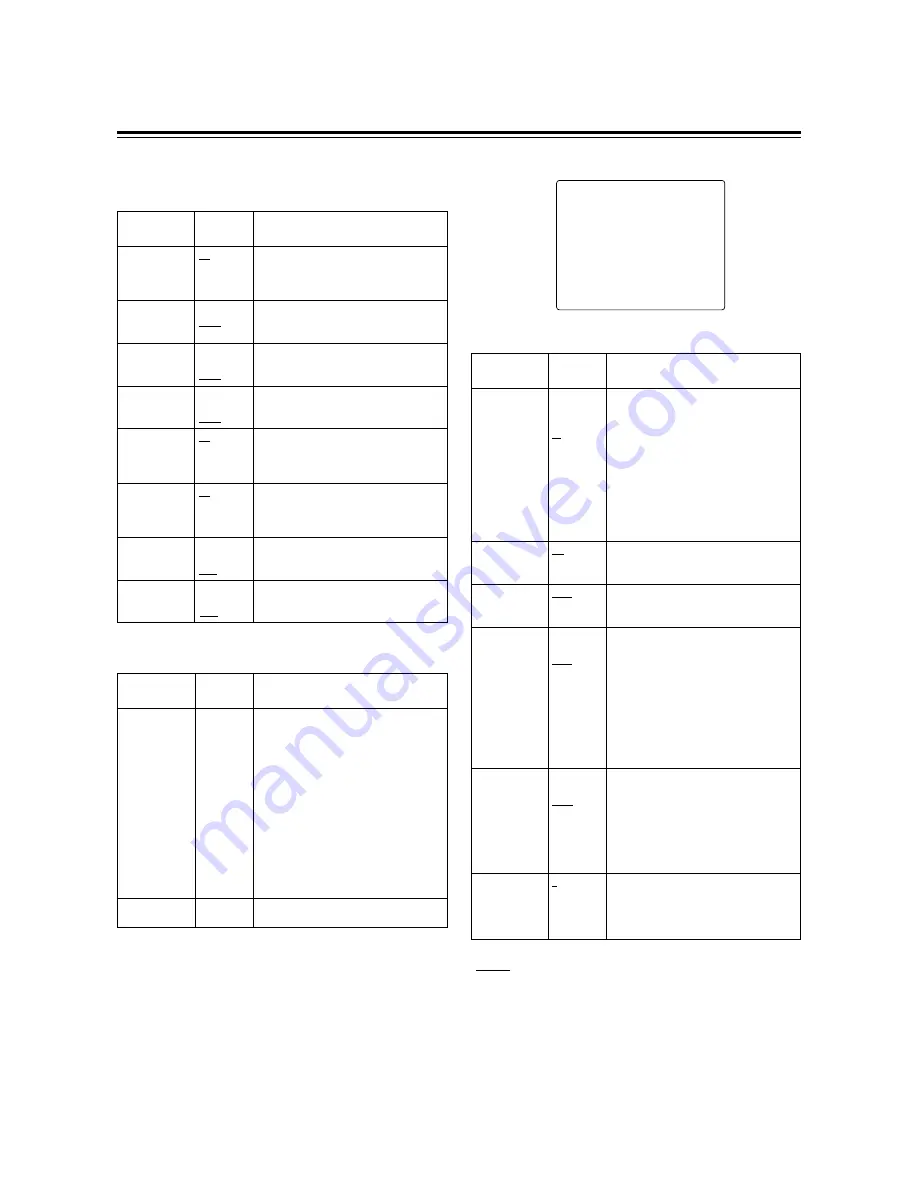
MAIN menu 2 of 2 (main menu)

#

NEXT

¢¢¢¢ 

MAIN 2/2 

¢¢¢¢

MARKER/ZEBRA..
VF DISPLAY 1/2..
VF DISPLAY 2/2..
! LED..
GENLOCK..
CAMERA ID..
TIME/DATE..
DIAGNOSTIC..

MARKER/ZEBRA

Item

Setting

options

Remarks

SAFETY ZONE

OFF
01

:

06

:

09

For selecting the shape of the safety
markers.
OFF: No markers are displayed.
01:

80% and 90% corner display

02:

80% corner display

03:

90% corner display

04:

80% and 90% box display

05:

80% box display

06:

90% box display

07:

16:9 picture frame and 90% of 16:9 display

08:

16:9 picture frame and 80% of 16:9 display

09:

16:9 picture frame (100%) display

ZEBRA2

ON
OFF
SPOT

For selecting the zebra 2 pattern type.
ON:

Zebra patterns 1 and 2 are
displayed.

OFF: Only zebra pattern 1 is displayed.
SPOT: Zebra pattern 1 is displayed from

the level set for ZEBRA1 DETECT
to the level set for ZEBRA2
DETECT.

VF DTL

1
2
3
OFF

For selecting VF DTL.
The higher the number, the more the detail
of the signals for the viewfinder is
emphasized.  When OFF is set, the detail
signals are not output.

CENTRE MARK

ON
OFF

For setting the centre marker display to ON
or OFF.
ON: Displayed

OFF: Not displayed

ZEBRA1 DETECT

070%

:

104%

For setting the boundary at which the zebra
1 pattern appears.

ZEBRA2 DETECT

071%

:

085%

:

105%

When the next menu item, ZEBRA2, is set
to SPOT or OFF:

>

This item sets the boundary at which the
zebra 1 pattern appears.

When the next menu item, ZEBRA2, is set
to ON:

>

This item sets the boundary level at
which the pattern is switched to zebra 1.

<Note>
The ZEBRA2 DETECT level must be set
higher than the ZEBRA1 DETECT level.

Menu contents

MAIN menu 1 of 2 (main menu)

LENS SHADING

Item

Setting

options

Remarks

SHADING (USER)

For performing shading compensation for
the USER lens.

MIC/AUDIO

Item

Setting

options

Remarks

FRONT MIC
POWER

ON
OFF

ON: Phantom power is supplied to the

front microphone.

OFF: Phantom power is not supplied to the

front microphone.

LINE CH2

+4dB
0dB
–6dB

For selecting the rear jack AUDIO CH2 line
input level.

FRONT MIC

–40dB
–50dB
–60dB

For selecting the camera mic input level.

REAR MIC CH2

–40dB
–50dB
–60dB

For setting the input mic level for the rear
jack AUDIO CH2 input.

MIC LOWCUT CH1

ON
OFF

ON: The low-cut filter is set to ON for the

CH1 mic input.

OFF: The low-cut filter is set to OFF for the

CH1 mic input.

MIC LOWCUT CH2

ON
OFF

ON: The low-cut filter is set to ON for the

CH2 mic input.

OFF: The low-cut filter is set to OFF for the

CH2 mic input.

LINE CH1

+4dB
0dB
–6dB

For selecting the rear jack AUDIO CH1 line
input level.

LENS SELECT

A
B
C
USER

For selecting the type of lens mounted on
the unit.
A:

S18 

a

6.7BERM4

S18 

a

6.7BRM4

S19 

a

6.5BERM4

S19 

a

6.5BRM4

YH18 

a

6.7IRS

YH12 

a

4.8IRS

B:

YH18 

a

6.7KRS/KP

YH14 

a

7.3KRS

YH12 

a

4.8KRS

S14 

a

7.5BRM4

S17 

a

6.6BRM4

C:

S14 

a

7.3BRM

USER:Lens other than A, B or C

REAR MIC CH1

–40dB
–50dB
–60dB

For setting the input mic level for the rear
jack AUDIO CH1 input.

” indicates the factory setting.

Summary of Contents for AG-DVC 200E

Page 1: ...Before attempting to connect operate or adjust this product please read these instructions completely AG E Digital Video Camera Recorder Digital Video Cassette ENGLISH ESPAÑOL ITALIANO FRANÇAIS DEUTSCH ...

Page 2: ...efboom LOC K CH1 RESET COUNTER AUDIO SELECT AUDIO IN AUTO MIC FRONT REAR MIC LIVE MAN TCG TC UB ON OFF CH1 CH1 BREAKER CH2 CH1 CH2 CH2 F RUN SET R RUN MIC POWER CH2 AUDIO LEVEL POWER WARNING QUICK FOCUS MODE CHECK SCENE FILE MONITOR AUTO IRIS MODE FULL AUTO VTR GAIN OUTPUT WHITE BAL MENU ON OFF POWER BACK L USER STD SPOT L 1 F1 F2 F3 F4 STD BARS CAM ON SAVE STBY H L M OFF AUTO KNEE PRST A B Back u...

Page 3: ...paristo valmistajan ohjeiden mukaisesti Lithium Battery Warning The lithium battery in this equipment must only be replaced by qualified personnel When necessary contact your local Panasonic supplier The lithium battery is a critical component type number CR2032 manufactured by Panasonic It must never be subjected to excessive heat or discharge It must therefore only be fitted in equipment designe...

Page 4: ...Time data settings 22 Setting the user s bit 22 Setting the time code 22 Scene files 23 Scene file function 23 Scene file setting method 23 Editing scene filenames Example USER files 23 Returning a scene filename to its default 24 How to use file select 24 List of scene file settings 25 List of file settings 25 Normal recording 26 Recording methods 26 Scene to scene continuity 26 Audio recording 2...

Page 5: ...settings Auto iris mode selection function This enables three auto iris settings to be selected The settings can easily be switched to match the shooting conditions Menu jog dial system A jog dial button enabling easy menu settings is provided on the front panel of the camera Features of the VTR unit DV format The VTR unit compresses the images using a component digital recording system that incor...

Page 6: ...0 L90 NP 1B 1 5 viewfinder AJ VF10 AJ VF15 Digital Video Camera Recorder AG DVC200E Note Checking the lens shading compensation This unit comes with a function which provides shading compensation for the lens Check that the compensation is optimum for the type of lens used For further details refer to Lens adjustments and checks page 15 Lens classification Lens type A B S18 a 6 7BERM4 S18 a 6 7BRM...

Page 7: ...med at this position than at the STBY position so that the battery will supply power to the unit for a longer period of time Compared with the STBY position more time is taken to start recording after the VTR START button is pressed When the switch is set to the SAVE position the VTR SAVE lamp inside the viewfinder lights up Note When the PAUSE TIMER time has elapsed in the STBY mode the unit is a...

Page 8: ...lashes in red to alert the user For further details refer to Warning system page 38 6 BREAKER switch If an excessively high current flows inside the unit due to some problem or other the circuit breaker is tripped and the power is automatically turned off to protect the unit Push this button in after conducting an inspection or repairs inside the unit If there are no problems the power will come b...

Page 9: ...g cord of the lens is connected to this jack For further details on the lenses that can be used refer to the operating instructions of the lenses concerned 8 MIC IN mic input jack XLR 3 pin The accessory microphone is connected to this jack The power for the microphone is supplied from this jack 2 Lens lever This lever is tightened to secure the lens after the lens has been attached to the lens mo...

Page 10: ... refer to Using the unit with external components page 29 1 2 3 4 6 7 5 ª 6 5 1 EJECT REW FF STOP PLAY PAUSE 9 8 8 REW rewind FF fast forward buttons lamps When one of these buttons is pressed in the stop mode the high speed playback rewind or fast forward mode is established and the corresponding lamp lights When one of these button is pressed in the playback mode the 4a speed playback rewind or ...

Page 11: ... instructions of the battery charger used Disconnect these Connect here Rubber caps Screws AU M402H battery case 1Connect the unit s cable with the cable of the AU M402H battery case 2Use a screwdriver to attach the AU M402H battery case to the unit The holes for tightening the screws can be seen when the cover is opened and the rubber caps are raised Use a screwdriver to tighten the screws and at...

Page 12: ...ng BATTERY on the sub menu screen Select NiCd12 if the NP 1B is to be used See page 34 Reference To remove the battery pack slide it in the opposite direction to the one in which it was attached while keeping the release lever on the battery holder pulled down all the way Release lever 2 Using the NP 1B battery pack made by Sony Before use charge the battery pack using the exclusive battery charge...

Page 13: ...ch to ON When an AC adapter other than the AJ B75 is to be used check the pin signals of the external DC input socket Notes When both a battery pack and an AC adapter have been connected the power supplied from the AC adapter takes priority It is also possible to attach remove a battery while the AC adapter is being used When an AC adapter is to be used the unit s POWER switch must be set to ON on...

Page 14: ...pod attachment Detaching the unit from the tripod attachment Red lever While pushing down the red lever move the black lever in the direction of the arrow and slide the unit toward the back to remove it Note If the pin of the tripod attachment fails to return to its original position after the unit has been detached again move the black lever in the direction of the arrow while pushing down the re...

Page 15: ...s 0 through 9 7 Symbols The setting menu is cleared and the unit s current status is displayed To change the back to press the JOG dial button when the is above the colon Setting the date and time 1 Proceed with the sub menu operation page 30 to open the TIME DATE screen 3 T I M E D A T E Y E A R 0 1 M O N T H 0 1 D A Y 0 1 H O U R 0 0 M I N U T E 0 0 T I M E D A T E S E T R E A D Y 2 Turn the JOG...

Page 16: ...ls the whole screen Check that the lens iris is between f 4 and f 11 Notes Flicker tends to occur under fluorescent lights mercury lamps and other such lighting conditions Use sunlight halogen lamps or a light source which rarely give rises to flicker If there is unevenness in the lighting the zebra pattern will no longer appear on some parts of the screen In this situation adjust the lighting pos...

Page 17: ...r available as an optional accessory 1 REC record lamp This lights up red during recording It flashes when an error has occurred For further details refer to Warning system page 38 3 BATT battery lamp This starts flashing several minutes before the battery voltage drops to the level where the battery can no longer be used and it remains lit when the battery can no longer be used To prevent an inte...

Page 18: ...the interval recording mode For further details refer to INTERVAL REC function page 28 5 1st line message display changes in switch settings AWB Ach K AWB Ach K UNDER AWB Ach K OVER AWB Bch K AWB Bch K UNDER AWB Bch K OVER AWB PRE K AUTO KNEE ON AUTO KNEE OFF GAIN dB FILTER SHUTTER OFF SHUTTER 1 IRIS MODE FULL AUTO ON FULL AUTO OFF SCENE FILE USER SCENE FILE 1 SCENE FILE 2 SCENE FILE 3 SCENE FILE ...

Page 19: ...d when the lens iris has been closed Note This item appears when using a lens equipped with a function that displays the aperture value FULL AUTO SCENE FILE display FULL Filename which has been set Displayed when the FULL AUTO switch has been set to ON Indicates the filenames 8 characters set for the scene files VTR warning display voltage warning display REC WARNING SLACK E HUMID SERVO RF TAPE NE...

Page 20: ...D 003 This lights during an INDEX search A positive number denotes an index count in the forward direction and a negative number denotes an index count in the reverse direction With each detection the value is decremented to zero and when the tape stops the remaining tape display is restored I Safety zone markers Corner 3 types Box 3 types 16 9 full box 3 types The safety zone markers selected for...

Page 21: ... Service Centre representative The gain switching circuit is automatically switched while the black balance is being adjusted Although flicker or noise may appear on the viewfinder screen this is not indicative of malfunctioning Automatic white balance adjustment Power line frequency Shutter speed 50 Hz OFF 60 Hz 1 60 OUTPUT AUTO KNEE switch WHITE BAL switch 1 Set the switches to the positions sho...

Page 22: ...and standard mode the shutter speed is set by selecting the SHUTTER switch position In the SYNCHRO SCAN mode the shutter speed can be easily changed by operating the JOG dial button 1 60 1 120 1 250 1 500 1 1000 1 2000 Shutter modes Setting the synchro scanning mode Setting the shutter mode and speed Shutter modes and shutter speeds that can be set Mode Shutter speed Applications For shooting fast...

Page 23: ...N to OFF and then back to ON again UBG now appears in the viewfinder Select a number for the flashing part by rotating the JOG dial button and press the JOG dial button to enter it When the number is entered the flashing moves to the next character on the right so that another number can be input in the same way until the user s bit is set 1 Set the COUNTER TC UB switch to UB 3 Set the TCG switch ...

Page 24: ...1 CH2 F RUN SET R RUN MIC POWER AUDIO QUICK FOCUS MODE CHECK SCENE FILE MONITOR AUTO IRIS MODE FULL AUTO VTR GAIN OUTPUT WHITE BAL MENU ON OFF POWER BACK L USER STD SPOT L 1 F1 F2 F3 F4 STD BARS CAM ON SAVE STBY H L M OFF AUTO KNEE PRST A B The scene file settings are changed using the SCENE FILE dial and the sub menu SCENE FILE screen To change the back to press the JOG dial button when the is ab...

Page 25: ...a file 9 Rotate the JOG dial button to move to the WRITE item 3 S C E N E F I L E N A M E E D I T U S E R T A R O F I L E N A M E U S E R F A C T O R Y F 1 F L U O F 2 S P A R K L N G F 3 C O O L F 4 R E T R O S T D F A C T O R Y W R I T E U S E R R E A D Y I N I T U S E R R E A D Y 10When the JOG dial button is pressed the following message is displayed 3 S C E N E F I L E N A M E E D I T U S E R...

Page 26: ...IDEO OUT MENU VIDEO OUT SEL REMOTE SELECT ON ENC LOCAL VTR FUNCTION UB MODE FIRST REC TC BACK TALLY FF REW SPEED AUDIO SAMPLING USER REGEN ON x100 48 K VTR OPTION TIME STAMP REC TIME INTERVAL TIME PAUSE TIMER NO REC 00m05s 00h0m010s 10 min Setting item Remarks BATTERY BATTERY SELECT TYPE A NEAR END TYPE A END TYPE B NEAR END TYPE B END 1 to 4 NiCd14 11 6 V 11 2 V 12 7 V 12 4 V MIC AUDIO FRONT MIC ...

Page 27: ...ECT button to open the cassette compartment and insert the cassette tape 4 Point the camera at the subject and adjust the lens iris focus and zoom 5 Press the VTR START STOP button to start the recording 6 Press the VTR START STOP button to stop the recording 1 2 POWER OFF ON u REC SAVE Recording methods Scene to scene continuity is possible after the tape has been allowed to run or after the cass...

Page 28: ...st the input levels of the CH1 and CH2 sound manually proceed as follows The audio input signals can be monitored through the monitor speaker or earphone When the PHONES jack is used no sound will be heard through the monitor speaker The volume of the monitored sound can be adjusted using the MONITOR control Note Howl may be caused if the volume of the audio monitor speaker is too high In this sit...

Page 29: ...ard or reverse direction for the number of times that corresponds to the number of times the FF or REW button was pressed Example Press the REW button 3 times The third index area back from the stop area is searched Viewfinder display IND 003 Press the FF button twice The second index area ahead from the stop area is searched Viewfinder display IND 002 To stop index search at any time press the ST...

Page 30: ...e used as a player by connecting it to a video component equipped with a DV connector using a DV cable In either case refer to the figure below for the connections Using the unit as a player Select 1394 as the REMOTE SELECT setting on the sub menu VIDEO OUT screen See page 34 The unit can now be controlled from the external video component with the DV connector DV IF connector DV cable Video compo...

Page 31: ...s the MENU button SCENE MAIN 1 2 MAIN 2 2 Press the MENU button Press the MENU button Press the JOG dial button Press the JOG dial button Press the JOG dial button Menu screen is cleared 5 5 Press the MENU button 5 Press the MENU button 5 N E X T MAIN 2 2 M A R K E R Z E B R A V F D I S P L A Y 1 2 V F D I S P L A Y 2 2 L E D G E N L O C K C A M E R A I D T I M E D A T E D I A G N O S T I C Rotate...

Page 32: ...RONT MIC POWER FRONT MIC REAR MIC CH1 REAR MIC CH2 MIC LOWCUT CH1 MIC LOWCUT CH2 LINE CH1 LINE CH2 VTR OPTION TIME STAMP INTERVAL REC REC TIME INTERVAL TIME PAUSE TIMER SW MODE LOW GAIN MID GAIN HIGH GAIN ATW SUPER V QUICK FOCUS FULL AUTO LENS SHADING LENS SELECT SHADING USER FILE READ FILE WRITE READ FACTORY SCENE FILE MAIN 2 2 MARKER ZEBRA VF DISPLAY 1 2 LED CAMERA ID DIAGNOSTIC SAFETY ZONE CENT...

Page 33: ... STR For selecting the low brightness black rise PRESS The black is compressed and the images appear tight NORM Standard setting STR The black is extended and the gradations in the dark areas are expanded COLOUR SKIN TONE Item Setting options Remarks PRE COLOUR TEMP 30 00 30 For finely adjusting the colour temperature from the white balance when the WHITE BAL switch is set to the PRE position This...

Page 34: ...LL AUTO ENABLE DISABLE For enabling or disabling the full auto function SCENE FILE ENABLE DISABLE For enabling or disabling the scene file function ENABLE The scene file function is enabled DISABLE The scene file function is restricted to the user files Menu contents SCENE MENU main menu indicates the factory setting PROCESS Item Setting options Remarks H DETAIL 10 00 10 For setting the amount of ...

Page 35: ...ted select the type of date and time to be superimposed with the TIME DATE item of VF DISPLAY 2 2 sub menu PAUSE TIME 3min 6min 10min For setting the time that is allowed to elapse before REC PAUSE is replaced with SAVE INTERVAL REC OFF ON ONE SHOT For setting whether to perform intermittent recording OFF Not performed ON Performed ONE SHOT Recording is performed once for the period set for REC TI...

Page 36: ...n appears When the next menu item ZEBRA2 is set to ON This item sets the boundary level at which the pattern is switched to zebra 1 Note The ZEBRA2 DETECT level must be set higher than the ZEBRA1 DETECT level Menu contents MAIN menu 1 of 2 main menu LENS SHADING Item Setting options Remarks SHADING USER For performing shading compensation for the USER lens MIC AUDIO Item Setting options Remarks FR...

Page 37: ... The CH1 and CH2 audio levels are displayed TAPE REMAIN ON OFF For setting the tape type and remaining tape display ON or OFF ON Displayed OFF Not displayed WHITE BAL ON OFF For setting the WHITE BAL switch position and ATW display ON or OFF ON Displayed OFF Not displayed The information to be displayed in the viewfinder is selected on this menu VF DISPLAY 2 2 Item Setting options Remarks SHUTTER ...

Page 38: ...isplayed W 0 dB Displayed at any gain setting except 0 dB SUPER V ON OFF For setting the LED display ON or OFF when SUPER V is ON ON Displayed OFF Not displayed WHITE ATW PRE OFF For setting the LED display ON or OFF when the WHITE BAL switch is at the PRE position or ATW has been set ATW Displayed in the ATW mode PRE Displayed when PRE is the position setting OFF Not displayed FILTER OFF W O No 1...

Page 39: ... still cannot be performed properly even after they have been cleaned turn off the unit s power and consult your nearest service centre SERVO WARNING lamp Flashes four times per second during recording and playback Tally lamp Flashes four times per second during recording and playback Viewfinder The SERVO display flashes during recording and playback Description of warning The servo is out of sync...

Page 40: ...usly push and rotate the EMERGENCY screw 1 Set the power to OFF 4 Remove the cassette 5 Return the rubber cap to its original position 2 As shown in the figure remove the rubber cap to reveal the EMERGENCY screw red 3 While pushing the screwdriver keep turning the EMERGENCY screw counterclockwise until the tape is ejected It takes about 20 turns for unloading to commence It takes about 90 turns fo...

Page 41: ...e lens cleaners available on the market to wipe the lens Never wipe the mirror under any circumstances If dirt or dust has adhered to the mirror blow it away using an air blower available on the market Cleaning inside the viewfinder Smear This may occur when extremely bright subjects are shot The higher the electronic shutter speed the more this phenomenon is liable to occur Phenomena inherent to ...

Page 42: ...ht Approx 3 kg main unit only CAMERA UNIT Pickup device 1 2 inch IT type CCD 480 000 pixels System RGB 3 CCD system Total number of pixels 795 H a 596 V Number of effective pixels 752 H a 582 V Spectral system f 1 4 prism system Internal filters 1 3200K clear 2 5600K 1 8ND 3 5600K 4 5600K 1 64ND Quantizing 10 bits non linear Sampling frequency 14 1875 MHz Digital signal processing 28 375 MHz Horiz...

Page 43: ...2 RCA a 2 6 dBu low impedance unbalanced PHONE OUT stereo mini jack 30 to 80 dBu Output Specifications VIEWFINDER Optional accessory AJ VF10 CRT 1 5 inch high resolution monochrome CRT Video system 625 lines 50 fields External controls Controls BRIGHT CONTRAST PEAKING Switches TALLY HIGH OFF LOW ZEBRA ON OFF ACCESSORIES Battery holder already installed on unit for Anton Bauer products Microphone T...

Page 44: ...F0401T1051 Printed in Japan VQT9278 1 E Matsushita Electric Industrial Co Ltd Central P O Box 288 Osaka 530 8691 Japan ...

Reviews: