background image


Getting started with the module for OEM   

10 

Getting started with the module for OEM 

Appendix A: Change EmStat USB connection to virtual 
COM port 

1.


Connect EmStat to the USB port. 

2.


Open FT_PROG (see 

http://www.ftdichip.com/Support/Utilities.htm

) 

3.


Click the “Scan and Parse” button 


4.


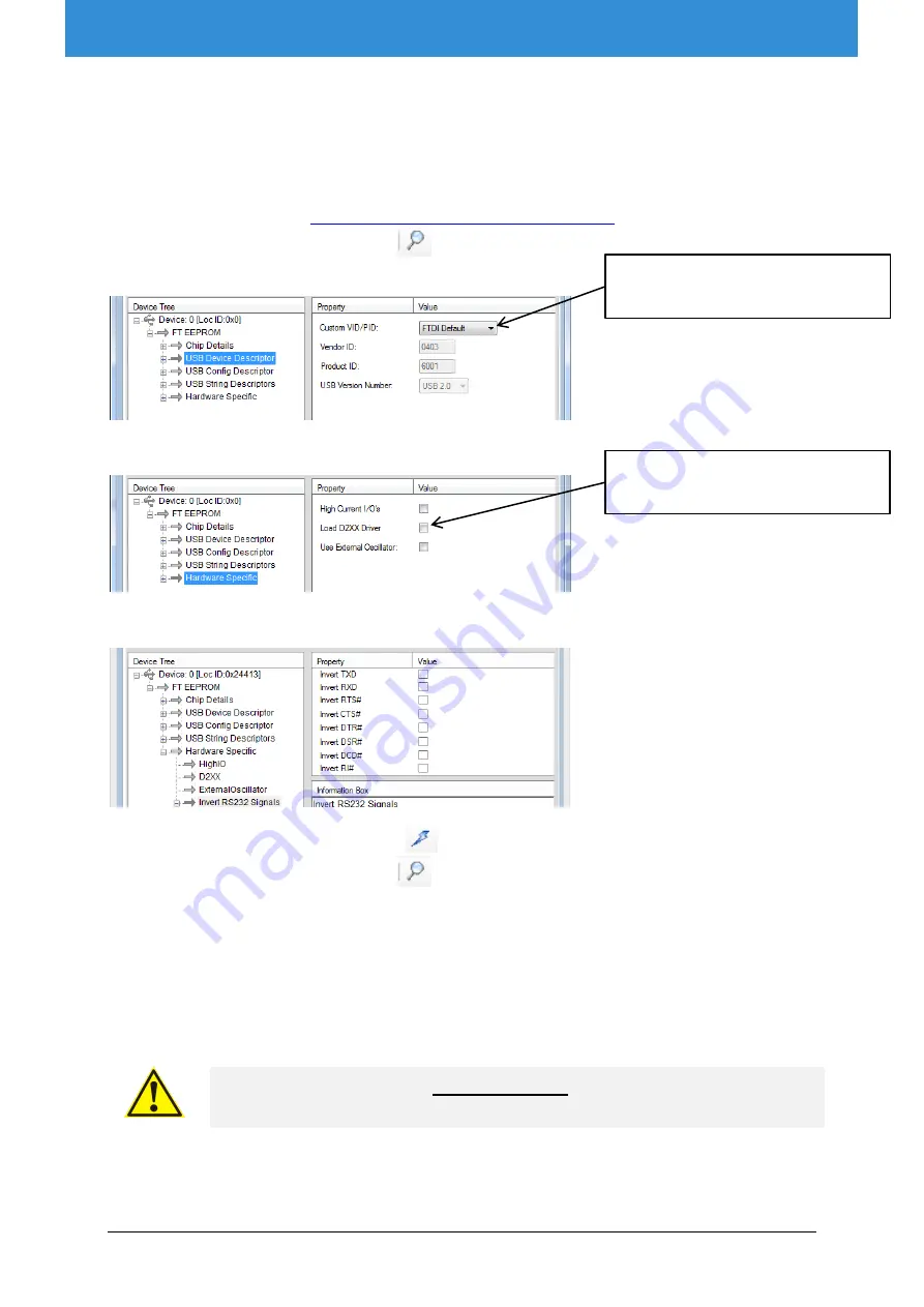
Change the Custom VID/PID to FTDI Default: 


5.


Uncheck the checkbox “Load D2XX Driver”:


6.


Make sure all 

Invert 

RS232 Signals”

 settings are unchecked: 


7.


Click the “Program Devices” button 


8.


Click the “Scan and Parse” button 

 again to check if the settings are written correctly, 

especially the invert DTR# setting. If this setting cannot be changed, please contact us. Your 
FT_PROG version might have a bug. 

9.


Remove the USB cable and insert again.  

10.


Your PC will now detect a virtual COM port which can be used to communicate with EmStat. 

11.


The com port number can be found in the Device Manager found in Windows Configuration. You 
can also press [windows key] + [pause] on your keyboard to find the Device Manager. 


 Make sure the USB chip is not programmed as VCP (Virtual COM port) 

when using the Rx/Tx lines on CON2 of the EmStat module. 


Select FTDI Default 

Uncheck “Load D2XX Driver”


Summary of Contents for EmStat3+

Page 1: ...Getting started with the EmStat3 module for OEM OEM Interface for electrochemical sensors Last revision January 28 2020 2020 PalmSens BV www palmsens com...

Page 2: ...r your convenience and may be superseded by updates It is your responsibility to ensure that your application meets with your specifications PALMSENS BV MAKES NO REPRESENTATIONS OR WARRANTIES OF ANY K...

Page 3: ......

Page 4: ...at communications 3 1 2 USB or serial TTL 3 1 3 Baudrate settings 4 1 4 Connecting to PC via RS232 converter 5 2 Printed Circuit Board Layout 5 CON1 description 6 2 1 CON2 description 6 2 2 Heat trans...

Page 5: ...n equivalent circuit fitting manually control the cell and many other things SDK s are available for WinForms WPF Android Xamarin UWP All SDK s can be downloaded from my palmsens com The instrument ca...

Page 6: ...r measurements Baudrate Max number of data points second Min interval time 230400 1000 1 00 ms 57600 197 5 07 ms It is possible to change the baudrate setting of the EmStat module in the firmware requ...

Page 7: ...ircuit Board Layout EmSta3 PCB layout The board has two pin headers CON1 and CON2 CON1 is used to connect for instance the MUX multiplexer or any other peripheral CON2 is used when serial TTL communic...

Page 8: ...powered from USB 5 V power supply 100 mA min 6 DGND 7 10 V analog adviced max 50 mA 8 Sense 9 AGND connect to metal housing cable shielding 10 WE 11 RE 12 CE The digital I O lines are at 5V 2 1 CON2...

Page 9: ...a thermal connection from the bottom side of the PCB to something which can absorb heat for instance using the thermal pad WX 3009 0227 6 from 3M Suggested heatsinks Heatsink 24 pin DIP Glue On BLK 5...

Page 10: ...N4 on page 5 Front view of socket Solder side of socket 1 4 2 3 4 1 3 2 1 RE blue connector or reference electrode 2 CE black connector or counter electrode 3 S red female male connector or sense 4 WE...

Page 11: ...supply from EmStat Connect CON2 Pin 8 download active low to CON2 Pin 6 GND Connect the power supply Run program Update firmware Press Connect Load firmware file ESx where x is the EmStat type and th...

Page 12: ...ck the Scan and Parse button again to check if the settings are written correctly especially the invert DTR setting If this setting cannot be changed please contact us Your FT_PROG version might have...

Reviews: