


M
A
IN
T
E
N
A
N
C
E
/
R
E
P
A
IR
T
R
O
U
B
L
E
S
H
O
O
T
IN
G
O
P
E
R
A
T
IO
N
A
S
S
E
M
B
L
Y
/
I
N
S
T
A
L
L
A
T
IO
N
S
A
F
E
T
Y
/
S
P
E
C
IF
IC
A
T
IO
N
S
G
E
T
T
IN
G
S
T
A
R
T
E
D
8
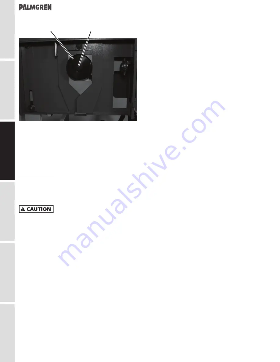
Figure 7.
112
114
Saw Blade Mounting Hardware
2. Remove bolt 114 and outside flange 112.
3. Mount the saw blade on the arbor with teeth of blade oiented
counterclockwise (the blade rotates counterclockwise in
normal operation).
4. Replace outside flange 112 and bolt. Turn blade clockwise
up against drive pins and securely tighten bolt.
5. Replace guard 121.
Cutting Coolant
For cooling of the circular blade, fill the tank with coolant
consisting of a mixture of water and AGIP AQUAMET 700 EP oil
with a percentage of 5-7%.
Lubrication
Do not operate this saw before adding
lubricant and ensuring proper oil level.
Failure to comply may damage the saw.


