3
GENERAL SAFETY INFORMATION (CONTINUED)
•
Always be sure machine is anchored securely to the floor or
bench.
•
Keep visitors at a safe distance from work area.
•
Keep children out of workplace. Make workshop childproof.
Use padlocks, master switches and remove switch keys to pre-
vent any unintentional use of power tools.
TOOL SHOULD BE MAINTAINED
•
Always unplug tool prior to inspection.
•
Consult manual for specific maintaining and adjusting procedures.
•
Keep tool lubricated and clean for safest operation.
•
Remove adjusting tools. Form habit of checking to see that
adjusting tools are removed before switching machine on.
•
Keep all parts in working order. Check to determine that the
guard or other parts will operate properly and perform their
intended function.
•
Check for damaged parts. Check for misalignment of moving
parts, binding, breakage, mounting and any other condition
that may affect a tool’s operation.
•
A guard or other damaged part should be properly repaired or
replaced. Do not perform makeshift repairs. (Use parts list
provided to order replacement parts.)
•
Never brush away chips while the machine is in operation. All
clean up should be done when the machine is stopped.
•
Never modify machine without consulting manufacturer.
•
Use sharp cutters and keep the tool clean for safest operation.
KNOW HOW TO USE TOOL
•
Use right tool for job. Do not force tool or attachment to do a
job for which it was not designed.
•
Disconnect tool when performing maintenance.
•
Avoid accidental start-up. Make sure that tool switch is in OFF
position before connection to air supply.
•
Do not force tool. It will work most efficiently at the rate for
which it was designed.
•
Leave hands free to operate machine. Protect hands from
possible injury.
•
Never leave a tool running unattended. Turn the power off and
do not leave tool until it comes to a complete stop.
•
Do not overreach. Keep proper footing and balance.
•
Always avoid contact with coolant; guard the eyes, especially.
•
All workpieces must be clamped to work table when using tap-
ping machine. It is unsafe to use your hands to hold any work-
piece.
•
Keep hands away from moving parts.
•
Know your tool. Learn the tool’s operation, application and spe-
cific limitations.
CAUTION:
Think safety! Safety is a combination of operator com-
mon sense and alertness at all times when tool is being used.
ASSEMBLY
Refer to Figures 2-11.
CAUTION:
Do not attempt assembly if parts are missing. Use this
manual to order replacement parts.
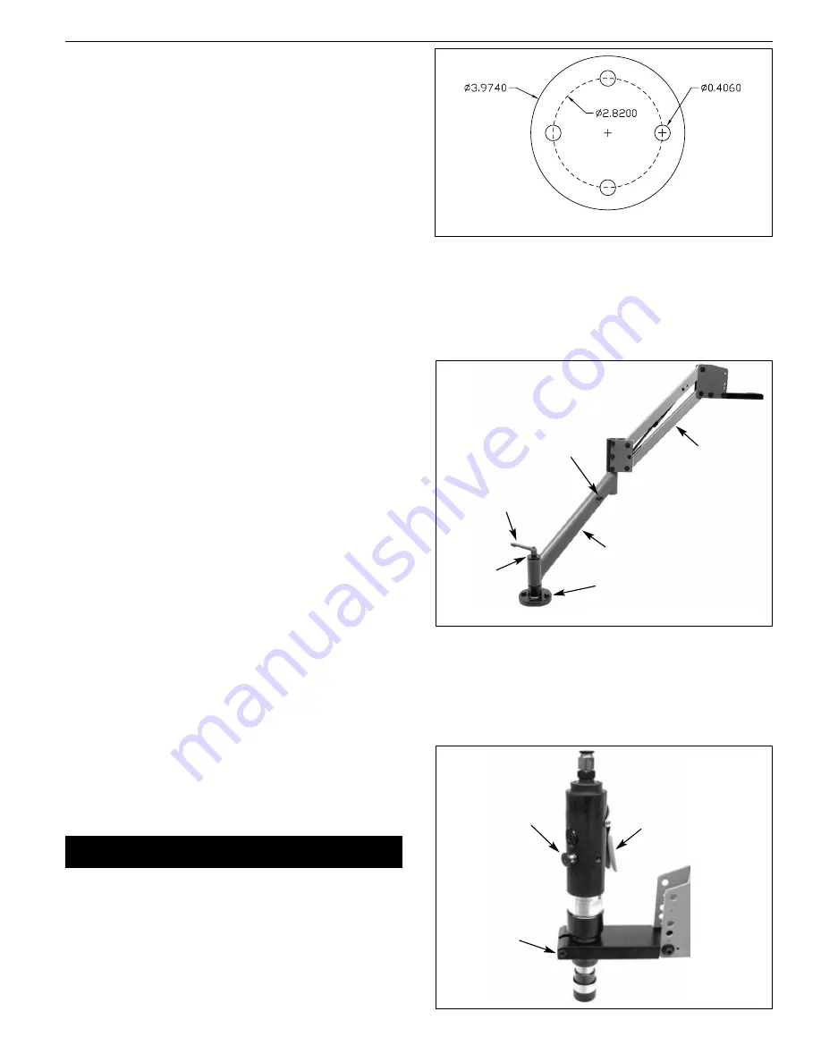
MOUNT BASE ASSEMBLY
Refer to Figure 2.
Mount base assembly to a solid horizontal surface using
3
⁄
8
” or
10mm bolts (hardware not provided). Figure 2 shows the footprint
of the base assembly.
ATTACH SUPPORT ARM AND CONTROL ARM
Refer to Figure 3.
•
Remove locking handle and washer from base assembly.
•
Slide support arm over base. Make sure lubrication unit
mounting screws are away from the base (see Figure 3).
•
Replace handle and washer to secure in position.
•
Insert control arm rod into support arm.
ATTACH SPINDLE MOTOR
MODELS 80420 AND 80421
Refer to Figure 4.
•
Insert spindle motor into bracket of control arm, make sure
spindle is completely seated into the bracket.
•
Secure spindle motor tightly into bracket using socket head bolt.
Palmgren Operating Manual & Parts List
80420, 80421, 80422 and 80423
Figure 2 –
Base Footprint (Dimensions in Inches)
Figure 3 –
Mount Support and Control Arms
Locking Handle
Base
Support Arm
Washer
Control Arm
Mounting
Screws
Figure 4
Operating Lever
Reverse Button
Socket Head
Bolt


