3
5
Routine maintenance
5.1 Pall filters do not normally require special attention
except for periodic monitoring of the pressure gauge
or electrical pressure warning device. Schedule
replacement of filter element every six months or sooner,
and have ample supply of spare elements available.
5.2 If external leakage is noted, replace O-ring at leak. If
leakage persists, check sealing surfaces for scratches or
cracks; replace any defective parts.
5.3 The pressure gauge and electrical pressure devices will
indicate when the element needs changing or because
of high fluid viscosity in ‘cold start’ conditions. If ‘cold
start’ conditions exist, see Section 6.2 and 6.3.
5.4 A dirty system can quickly plug a new filter element,
especially with Pall high efficiency filter media. It may
require one or two initial element changes to stabilize
element life. If element life is short or differential
pressure is excessive, filter may be undersized; refer to
the sizing and selection section of the product literature
or contact your local Pall representative.
5.5 Make sure element change labels are clean and
undamaged. Replace illegible labels with the appropriate
new labels.
6
Differential pressure devices
6.1 The pressure gauge and electrical pressure devices will
indicate when the element needs changing or because
of high fluid viscosity in ‘cold start’ conditions.
6.2 If a pressure gauge is fitted and shows high pressure
during ‘cold start’ conditions, check that the pressure
returns to a ‘normal’ reading when the normal operating
temperature is reached. If the gauge continues to show
high pressure after system warm-up, replace the filter
element.
6.3 If the electrical pressure switch actuates (e.g. red light
comes on) during cold start, continue operating until the
signal (red light) goes out as system warms to normal
operating temperature. This feature can be used as
‘warm up’ indication in operating procedures. If the
warning signal (red light) remains or appears when
system is warm, replace the filter element.
6.4 Use of both positive indication (green light) and negative
indication (red light for dirty element) is recommended to
effectively monitor filter element life.
6.5 Electrical pressure switch specifications and wiring
instructions:
Pressure switches mount with a 1/8” NPT thread.
Typical AC switch rating dependent on indicator
option:
5 AMP - 250VAC, 110 VAC
DC switch rating:
5 AMP 24VDC Normally Open, when not pressurized.
Wetted parts are Brass. Switches are pre-set:
1.1 bar (16 psi) or 2.4 bar (35 psi) depending on bypass
valve setting.
Maximum system pressure 10 bar (150 psi)
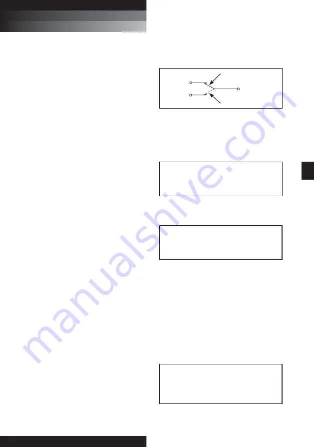
Electrical differential pressure switch operation:
When preset differential pressure is exceeded continuity
switches from Normally Closed (NC) - Common to Normally
Open (NO) - Common.
When differential pressure decreases below the pre-set
value, continuity returns to Normally Open (NO) - Common to
Normally Closed (NC) - Common.
ENGLISH
UT310
UT310 Series
RETURN LINE IN-TANK FILTERS
s e r v i c e
i n s t r u c t i o n s
Figure 1
- Switch Circuit Diagram
COMMON
NORMALLY
CLOSED
(NC)
NORMALLY
OPEN (NO)
LOW DIFFERENTIAL PRESSURE
HIGH DIFFERENTIAL PRESSURE
See individual indicator options for connection details.
7
Filter element servicing
During servicing, the external surfaces of the filter assembly
must be cleaned to remove any dust deposits.
Servicing must be conducted using suitable tools that do not
present a hazard.
Servicing must not be carried out when a potentially explosive
atmosphere is present.
Refer to Service Parts List (Section 9) for item numbers for
applicable replacement element series. Remove and replace
element as follows:
7.1 Turn off and depressurize the system.
7.2 Unscrew and remove filter cover assembly (2) from head
assembly (1) counterclockwise when viewed from above.
It may be necessary to use a correct sized wrench on
the hexagon on the filter cover assembly (2) to loosen
the cover initially. Check that the O-rings are not
damaged.
Note: The UT319 series assembly is equipped with Pall’s
‘Auto-Pull’ element extraction mechanism to facilitate element
removal. While removing the cap, tabs on the element endcap
lock into hooks in the cap and the element is automatically
pulled from the nipple.
7.3 Remove filter element (8) and carefully inspect the
surface for visible contamination. Normally no dirt
should show, but visible dirt or particles can be an early
warning of system component failure. Discard both the
filter element and its O-rings. The filter element is not
CLEANABLE. Any attempt to clean the filter element
can cause degradation of the filter medium and allow
contaminated fluid to pass through the filter element.
WARNING:
FAILURE TO DEPRESSURISE THE FILTER
BEFORE SERVICING ELEMENT COULD RESULT
IN EXPLOSIVE LOSS OF FLUID, DAMAGE TO
EQUIPMENT AND POSSIBLE PERSONAL INJURY.
WARNING:
DO NOT ATTEMPT TO CLEAN OR RE-USE THE
ELEMENT.
ONLY USE GENUINE PALL REPLACEMENT FILTER
ELEMENTS. USE OF SUBSTITUTE ELEMENTS MAY
INVALIDATE PRODUCT WARRANTY.
CAUTION:
Filter elements should be replaced upon indication or
at specified intervals, six months maximum. Failure
to change the element will cause the filter to go on
bypass.


