7
Electrical Installation
Revision 1.3
- 26 -
7.7
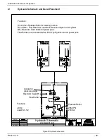
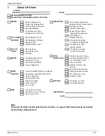
Electrical schematic of gate
M
o
to
r
S
o
le
n
o
id
1
2
V
P
o
w
e
r
R
e
le
a
se
V
a
lv
e
15
A fu
se
2
h
o
t
co
n
tr
o
l p
o
w
e
r
fr
o
m
f
u
se
4
c
o
n
tr
o
l p
o
w
e
r
fr
o
m
o
n
-o
ff
s
w
itc
h
5
u
p
f
u
n
ct
io
n
6
d
o
w
n
f
u
n
ct
io
n
4
4
2
2
2
h
o
t
fr
o
m
f
u
se
4
c
o
n
tr
o
l p
o
w
e
r
6
d
o
w
n
5
u
p
6
6
5
4
c
o
n
tr
o
l p
o
w
e
r
co
n
tr
o
l w
ir
e
d
e
sc
ri
p
tio
n
gro
und
st
ud
Pum
p u
nit
6
d
o
w
n
5
u
p
Re
lea
se
val
ve
x 2
@
cyl
ind
er
HA
CK
BA
RT
H
IL
P
C
o
n
tr
o
l s
w
itc
h
s
e
tu
p
C
a
b
o
n
/o
ff
s
w
itc
h
Figure 27 Electrical wiring schematic


