


44
Installing and connecting the platform
9.3
Bolting the platform to the first tilt cylinder
Depending on your tail lift model, you will need to bolt one or two tilt
cylinders to the platform. If your tail lift is equipped with two tilt
cylinders, you should initially only bolt one tilt cylinder to the
platform.
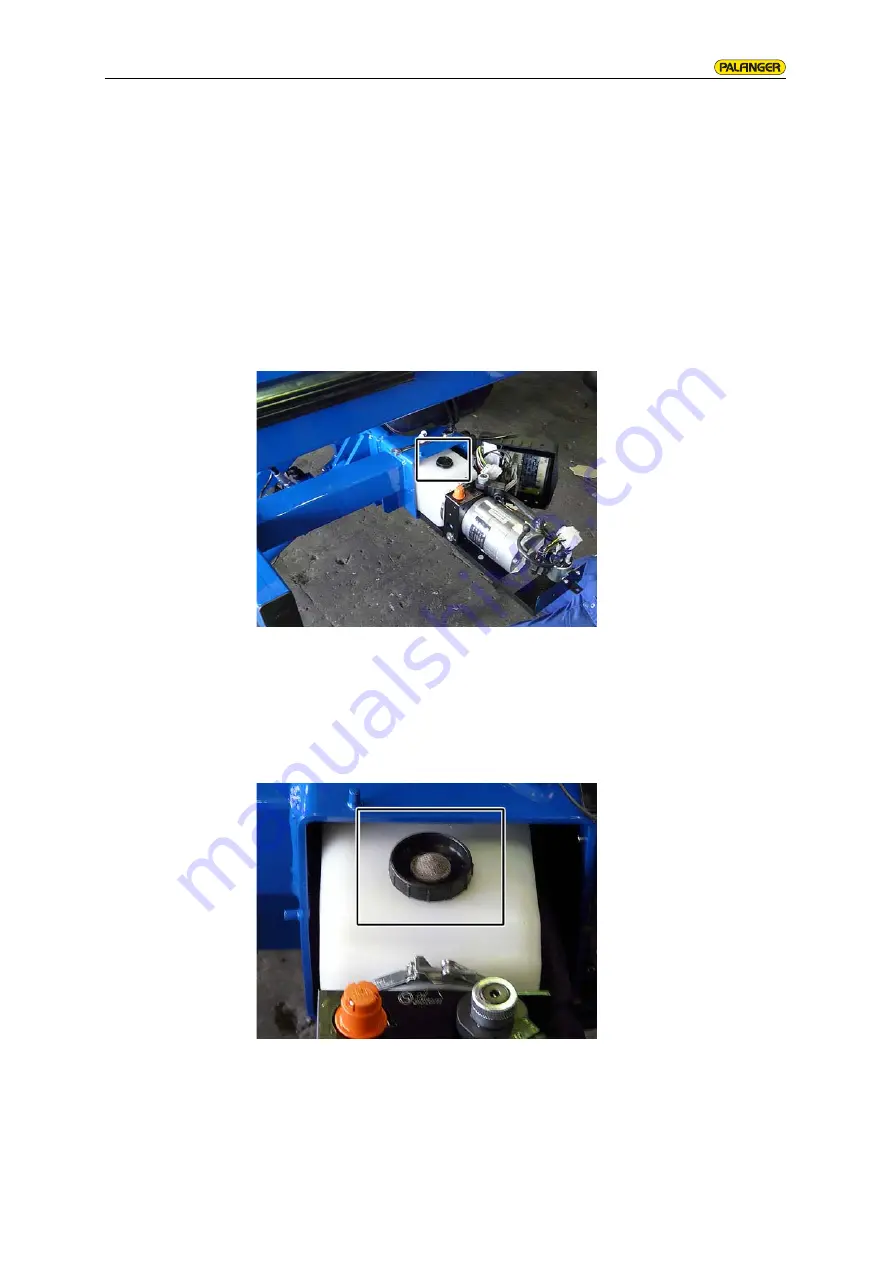
Inserting the air
filter (option)
Depending on the hydraulic unit manufacturer, you will have remove
the plug screw of the oil tank and replace with an air filter, before you
can bolt the platform to the first tilt cylinder.
Open the sealing cap on the hydraulic unit and carefully pull
the hydraulic unit out.
Remove the oil tank screw plug.
Insert the enclosed air filters.
Summary of Contents for C1500L
Page 2: ...MBB C 1500 L THE EFFICIENT AND FUNCTIONALLY TAIL LIFT...
Page 4: ...PALFINGER TAIL LIFTS ASSEMBLY INSTRUCTIONS TAIL LIFTS STANDARD...
Page 5: ......
Page 7: ......
Page 66: ......
Page 68: ...PALFINGER TAIL LIFTS OPERATING INSTRUCTIONS TAIL LIFTS...
Page 69: ......
Page 108: ...41...
Page 138: ...71...
Page 142: ...75...
Page 146: ...79...
Page 164: ...97...
Page 240: ...173 Retractable Tail Lift MBB R 1500 L FLAT 99 553 98 01 00 00 3 F LIFT CYL LIFT CYL...
Page 242: ...175 Foldable Tail Lift 93 505 60 08 00 00 L R2 R1 A DBV1 M A S1 S2 TILT CYLINDER TILT CYLINDER...
Page 243: ...176 Foldable Tail Lift 02 528 60 08 00 00 B M A R1 A DBV1 M S1 LIFT CYLINDER...
Page 252: ...PALFINGER TAIL LIFTS OPERATING INSTRUCTIONS TAIL LIFTS...
Page 253: ......
Page 292: ...41...
Page 322: ...71...
Page 326: ...75...
Page 330: ...79...
Page 348: ...97...
Page 424: ...173 Retractable Tail Lift MBB R 1500 L FLAT 99 553 98 01 00 00 3 F LIFT CYL LIFT CYL...
Page 426: ...175 Foldable Tail Lift 93 505 60 08 00 00 L R2 R1 A DBV1 M A S1 S2 TILT CYLINDER TILT CYLINDER...
Page 427: ...176 Foldable Tail Lift 02 528 60 08 00 00 B M A R1 A DBV1 M S1 LIFT CYLINDER...