background image

Direct calibration of P1 / P9 speeds: parameters UUE / UEn 


To regulate on air the 

P1 / P9

 fan speeds follow the procedure: 

ƒ


Chose modality MANUAL 

ƒ


Set the fan’s speed 

P01

 o 

P9


ƒ


Enter the SECONDARY Menu following the above procedure 

ƒ


Select the parameter 

UUE / UEn


and modify it until the desired value: 

in this way it is possible to control the two speeds directly 

ƒ


Memorise pushing button 

P4 

ƒ


To exit wait about 5 seconds


4.2  PLUGGING IN PROBE – THERMOSTAT 

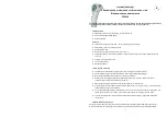
4.2.1  Aeraulic probe 

Installing the probe on the aeraulic tube (hot air) 30 cm far  
from the fireplace’s exit or 30 cm far from the mouth’s exit . 
To install:  
1.


Drill the tube 

2.


Insert in the probe’s support a washer and insert the probe in the tube 

3.


In the internal part of the tube screw the nut to fix the probe’s support to the tube 

4.


Insert the probe through the probe-locker 

5.


Screw the probe- locker in the probe’s support to block the probe without moving the support 

4.2.2  Thermostat 

Switch the thermostat in the right screwed place (M4) in the fireplace. 

4.3   CHANGE THE INPUT CONFIGURATION 

To enter the 

Cod

 parameter enter the secondary menu  

ƒ


Push together buttons 

P2 

and

 P3 

for about 5 seconds to enter modify parameters 

ƒ


Visualise parameters using the button 

P2 or P3

, until the parameter  

Cod


ƒ


Visualise the parameter’s value 

Cod

 pushing 

P4


ƒ


Modify the parameter’s value 

Cod

 with buttons 

P2 

or 

P3:


ƒ


In Probe: 

‘1’


ƒ


In Thermostat:  ‘2‘ 


ƒ


Memorise data with button 

P4


ƒ


Wait for about 5 seconds to exit 

ƒ


Stop and give supply to the controller


ƒ


If the input is a 

Probe

 the parameter 

Cod

 should be: 

[

Cod

 = 1

]

ƒ


If the input is a 

Thermostat

 the parameter 

Cod

 should be:

 [

Cod

 = 2

]


4.3.1   Particular case tangential Fan (002520016) with thermostat 

If the thermostat is wired in series to the fan make a bridge on the probe connector (9-10) 


4.4


ELECTRICAL CONNECTION SPARK KIT


ƒ


Connect the contact PULS of the kit Spark to the connectors 5-6 of the controller  

ƒ


Connect the contact SPR of the kit Spark to the connectors 7-8 of the controller 

Now feeding the spark kit and pushing the flame icon the spark kit is active. 


4.5 Configuration 

errors 

There could be two error’s conditions in the product’s configuration: 

A.


Cod = 1 

but input 

Thermostat


ƒ


Fire off appears 

Lo 

ƒ


Fire on appears 

Hi

 with acoustic signal on. 

B.


Cod = 2 

but input aeraulic 

Sensor


Feeding the controller appears on the display 

Err

.


4.6  INSTALLING RULES 


ATTENTION 

-


Avoid join together the probe’s cables with power’s cables. 

-


Provide the system’s feeding with a bipolar switch according to the actual rules and with opening 
distance  of the contacts of at least 3 mm for each pole. 

-


Installation and the electrical connection of the device have to be made by experienced personal and 
with appropriate equipping. 

-


Before the connection be aware that the electrical feeding is not connected.. 

GB

Sensor

Locker

Support

Probe

Nut

Tube

Summary of Contents for FC 810

Page 1: ...l tasto P4 si visualizza la modalità corrente segnalata dal display e dal relativo led Tramite successivi semplici pressione del tasto P4 si selezione in modo ciclico una delle tre tipologie di funzionamento segnalate dal display e dal relativo led Dopo 3 secondi l impostazione viene automaticamente memorizzata e si visualizza la velocità attualmente in uso Selezione Velocità di Funzionamento Tram...

Page 2: ...sattivata per 5 minuti tramite la pressione di un tasto Trascorso tale tempo se la condizione di allarme permane viene di nuovo attivata 3 3 SEGNALAZIONE DI GUASTI O ALLARMI La centralina prevede la segnalazione di guasto alla Sonda Cod 1 Messaggi lampeggiante di segnalazione guasto Lo indica un fuori scala verso il basso temperatura sotto 0 C Sonda interrotta Hi indica un fuori scala verso l alto...

Page 3: ...sto P4 Modificare il valore del parametro Cod tramite i tasti P2 o P3 Ingresso Sonda 1 Ingresso Termostato 2 Memorizzare il dato tramite il tasto P4 Attendere circa 5 secondi per uscire dalla modifica Togliere e ridare alimentazione alla centralina Nel caso in cui l ingresso utilizzato sia una Sonda il parametro Cod dovrà essere Cod 1 Nel caso in cui l ingresso utilizzato sia un Termostato il para...

Page 4: ...d Pressing again the P4 key select cyclically one of the three functioning typologies signalled by the display and by the led After about 3 seconds the setting is automatically memorised and the current speed is visualised Selection functioning speed Pressing P2 or P3 keys the setting of the current fan speed is visualised or modified P0 off only in MANUAL modality P1 minimum speed P10 maximum spe...

Page 5: ...obe Cod 1 Blinking message for the failure signal Lo indicates a low temperature temperature under 0 C Probe open disconnected Hi indicates a high temperature temperature over 180 C Probe in short circuit 4 0 MANUAL FOR THE INSTALLER All the following procedures have to be made by experienced and qualified personal because wrong parameters changing could make the product not adequate for a good fu...

Page 6: ...y the parameter s value Cod with buttons P2 or P3 In Probe 1 In Thermostat 2 Memorise data with button P4 Wait for about 5 seconds to exit Stop and give supply to the controller If the input is a Probe the parameter Cod should be Cod 1 If the input is a Thermostat the parameter Cod should be Cod 2 4 3 1 Particular case tangential Fan 002520016 with thermostat If the thermostat is wired in series t...

Page 7: ...alisiert wird Den P4 Schlüssel das auserwähltes zyklisch wieder betätigen von den drei arbeitenden Typologieern signalisierte durch die Anzeige und durch geführt Nachdem ungefähr 3 Sekunden die Einstellung automatisch memoriert ist und die gegenwärtige Geschwindigkeit wird sichtbar gemacht Arbeitende Gescwindigkeit wahlen Das Betätigen von von P2 oder von von P3 befestigt die Einstellung der gegen...

Page 8: ...ignal konnte für 5 Minuten eine Taste betätigend entaktiviert werden Nach 5 Minuten wenn ist es gibt wieder Zustände der Warnung es wird aktiviert wieder 3 3 AUFALL ODER WARMESIGNALE Der Regler hat den Signalausfall der Fühler Cod 1 Blinkanzeige fur das Ausfallsignal Lo zeigt eine niedrige Temperatur an Temperatur unter 0 C Fühler unterbrochen Hi zeigt ein Hochtemperatur Temperatur uber 180 C Fühl...

Page 9: ...r mit P4 Andern Parameter Cod mit P2 oder P3 In Fühler 1 In Thermostat 2 Memorisieren Sie Daten mit taste P4 Warten Sie 5 Sekunden herauszunehmen Stoppen Sie und geben Sie Speisung zum Regler Wenn der Eingang ein Sensor ist sollte der Parameter Kodex sein Cod 1 Wenn der Eingang ein Thermostat ist sollte der Parameter Kodex sein Cod 2 4 3 1 Bestimmten Falles mit Tangentiale Machine 002520016 mitThe...

Page 10: ...2 Presione el botón P4 para visualizar la modalidad actual que señalarán la pantalla y el led correspondiente Presione posteriormente el botón P4 para seleccionar en modo cíclico una de las tres tipologías de funcionamiento mostradas por la pantalla y el led correspondiente Después de unos tres segundos la programación se memoriza automáticamente y se visualiza la velocidad actual en uso Selección...

Page 11: ...otón Transcurrido este tiempo si las condiciones de la alarma persisten se vuelve a activar 3 3 INDICACIÓN DE AVERÍA O ALARMAS El cuadro de control prevé la indicación de avería en la Sonda Cod 1 Mensajes parpadeantes de indicación de avería Lo indica un fuera de escala hacia abajo temperatura por debajo de 0ºC Sonda interumpida Hi indica un fuera de escala hacia arriba temperatura por encima de 1...

Page 12: ...ar el valor del parámetro Cod pulse el botón P4 Para modificar el valor del parámetro Cod utilice los botones P2 o P3 Entrada sonda 1 Entrada termostato 2 Memorice el dato pulsando el botón P4 Espere unos cinco segundos para salir de la modificación Quite y restituya la alimentación al cuadro de control Si la entrada es un sensor el parámetro Cod debe ser Cod 1 Si la entrada es un sensor termóstat...

Page 13: ...a semple pression de la touche P4 on visualise la modalité courant signalée du display e du relatif led Par successives simples pressions de touche P4 on selectionne dans une facon cyclique une des trois typologies de fonctionnement signalées du display e du relatif led Après 3 secondes la selection est automatiquement memorisée et on visualise la vitesse actuellement en utilisation Selectionner V...

Page 14: ... pendent 5 minutes par la pression sur une touche Après ce tempe si la condition d alarme continue elle est ancore activée 3 3 SIGNALISATION DES PANNES OU ALARMES La centrale electronique prevoit la signalisation de panne à la Sonde Cod 1 Message lumineux de signslisation de panne Lo indique une température anormalement bass temperature sous 0 C Sonde interrompu Hi indique une température anormale...

Page 15: ...leur du parametre Cod par le touches P2 ou P3 Entrée Sonde 1 Entrée Thermostate 2 Memoriser le donné par la touche P4 Attendre 5 sec pour sortir de la modification Enlever et redonner alimentation à le termoregulateur Dans le cas lequel l entrée utilisée soit une Sonde le paramètre Cod devra être Cod 1 Dans le cas lequel l entrée utilisée soit une Termostato le paramètre Cod devra être Cod 2 4 3 1...

Page 16: ...ufacturer reserves the right for changing technical data and features without prior notice The consumer is guaranteed against any lack of conformity for 24 months from the delivery time according to the European Directive 1999 44 EC The full text of guarantee is available on request from the seller The company does not answer for damages due to a wrong wiring or improper use of the device Nach der...

Reviews: