55
51-3000
OPTION - HYDRAULIC LIFT KITS
Installation
Figure 1 shows the lift kit fully installed.
1. Remove the electric actuator and wiring if
installed on the drive assembly.
2. Place the lift plate on the pin welded to the
lift linkage. Clamp the plate. Center mark the
hole. Remove the plate and drill a hole in the lift
linkage with a 17/32 inch bit.
3. Attach the lift plate to the lift linkage with a 1/2-
13 x 1 1/4 cap screw, flat washer, lock washer
and nut. Slide a bushing onto the pin on the lift
linkage and install a hairpin clip.
4. Place the rod end of the cylinder on the pin;
secure with a hairpin clip.
5. Insert a bushing in the barrel end of the cylinder.
Fasten the cylinder to the tab on the drive
assembly using a pin and hairpin clip.
6. Install elbow fittings, hoses and quick coupler
fittings on the cylinder.
7. Connect quick couplers to tractor remotes.
8. Lift and lower the sweeper to test cylinder
functions.
9. Adjust the cable.
• If the brush head assembly does not raise
enough, decrease the amount of cable
between the uprights.
• If the brush head assembly raises too much,
increase the amount of cable between the
uprights.
figure 1
Summary of Contents for Sweepster M24 Series
Page 2: ...2 51 3000 NOTES...
Page 29: ...29 51 3000 DRIVE ASSEMBLIES 1 WAY Assembly 11 17142...
Page 31: ...31 51 3000 DRIVE ASSEMBLIES 1 WAY Assembly 11 17390...
Page 33: ...33 51 3000 DRIVE ASSEMBLIES 1 WAY Assemblies 11 17186 11 17187...
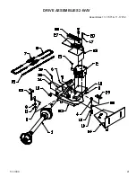
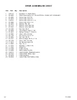
Page 35: ...35 51 3000 DRIVE ASSEMBLIES 2 WAY Assemblies 11 17100 11 17101...
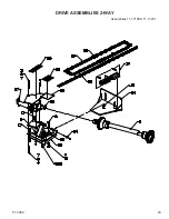
Page 39: ...39 51 3000 DRIVE ASSEMBLIES 2 WAY Assemblies 11 17177 11 17182...
Page 41: ...41 51 3000 DRIVE ASSEMBLIES 2 WAY Assemblies 11 17371 11 17372...
Page 43: ...43 51 3000 DRIVE ASSEMBLIES 2 WAY Assemblies 11 17198 11 17231...

