background image

MR955512

11

DECALS

DECAL PLACEMENT

GENERAL INFORMATION


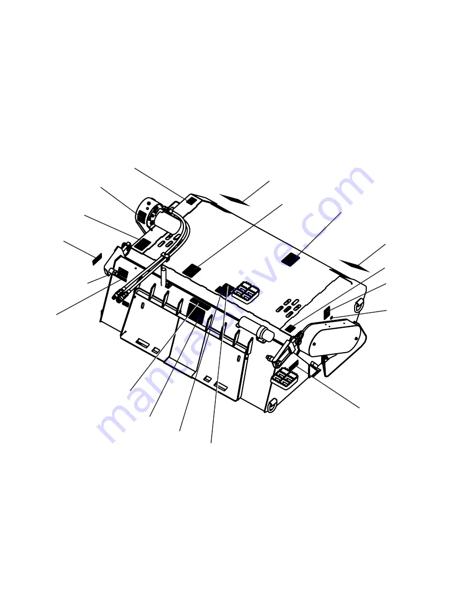
The diagram on this page shows the location of the decals used on your attachment.

The decals are identified by their part numbers, with reductions of the actual decals located on

the following page. Use this information to order replacements for lost or damaged decals. Be

sure to read all decals before operating the attachment. They contain information you need to

know for both safety and product longevity.

IMPORTANT:

 Keep all safety decals clean and legible. Replace all missing, illegible, or damaged safety decals. 

When replacing parts with safety decals attached, the safety decals must also be replaced. Safety decals are 

available, free of charge, from your local dealer or Paladin.

REPLACING SAFETY DECALS

: Clean the area of application with nonflammable solvent, then wash the same 

area with soap and water. Allow the surface to fully dry. Remove the backing from the safety decal, exposing the 

adhesive surface. Apply the safety decal to the position shown in the diagram above and smooth out any bubbles. 

# 50-0724

# RDL3102

SERIAL TAG 

LOCATION

# 50-0769

# RDL3100

# RDL3100

# RDL3178

# RDL3102

# 50-0909

# 50-0737

# 50-0737

# 50-0769

# RDL3180

# 41204

# RDL3101

# 50-10017

# 40590

# RDL3178

Summary of Contents for FFC PREPARATOR LAF3566

Page 1: ...ber E042020 and UP Release Date February 2019 Rev 6 PREPARATOR 800 456 7100 I www paladinattachments com 2800 N Zeeb Rd Dexter MI 48130 United States of America Copyright OPERATOR S MANUAL SERIAL NUMB...

Page 2: ......

Page 3: ...16 Skid Shoe Adjustment 16 17 Operation 17 20 Rock Collection Soil Tillage Foliage Uprooting Roughing Foliage Collection Finish Pass Dumping 20 Storage 20 Removal From Storage 21 Lift Points 21 Tie Do...

Page 4: ...MR955512 4 THIS PAGE IS INTENTIONALLY BLANK...

Page 5: ...the operator Make sure the equipment is operated only by trained individuals that have read and understand this manual If there is any portion of this manual or function you do not understand contact...

Page 6: ...ating Visually inspect your equipment before you start and never operate equipment that is not in proper working order with all safety devices intact Check all hardware to ensure it is tight Make cert...

Page 7: ...YDRAULIC FLUID PRESSURE Hydraulic fluid under pressure can penetrate the skin and cause serious injury or death Hydraulic leaks under pressure may not be visible Before connect ing or disconnecting hy...

Page 8: ...ired Wear the protective equipment specified by the tool manufacturer SAFELY OPERATE EQUIPMENT Do not operate equipment until you are completely trained by a qualified operator in how to use the contr...

Page 9: ...paint stripper remove stripper with soap and water before welding Remove solvent or paint stripper containers and other flammable material from area Allow fumes to disperse at least 15 minutes before...

Page 10: ...regula tions that may affect you Do not drive close to ditches excavations etc cave in could result Do not smoke when refueling the prime mover Allow room in the fuel tank for expansion Wipe up any sp...

Page 11: ...d legible Replace all missing illegible or damaged safety decals When replacing parts with safety decals attached the safety decals must also be replaced Safety decals are available free of charge fro...

Page 12: ...SURE FLUID HAZARD RDL3101 WARNING ROLLOVER DECALS RDL3178 CAUTION NOT A STEP 50 0769 LIFT POINT 50 0909 MANDATORY ACTION LUBE CAUTION 40590 DO NOT OPERATE USING HI FLOW HYDRAULIC SYSTEMS Maximum 25 GP...

Page 13: ...clear Stay at least 9 feet away RDL3100 50 10017 WARNING AVOID SERIOUS INJURY DECALS NOTE CONTACT YOUR LOCAL DEALER FOR MODEL NUMBER AND LOGO DECALS RDL3102 WARNING SHIELD RDL3180 IMPORTANT CHAIN TENS...

Page 14: ...ilure to do so could result in separation of the attachment from the prime mover 3 Lower the unit to the ground and relieve pressure to the auxiliary hydraulic lines 4 Following the safety shut down p...

Page 15: ...could get wrapped around the drum The Preparator is not designed for removing large mounds of soil and or filling in large or deep holes Other equipment should be used to obtain a reasonable starting...

Page 16: ...t could suddenly collapse or shift positions Do not use wood or steel blocking that shows any signs of material decay Do not use blocking that is warped twisted or tapered Failure to obey this warning...

Page 17: ...ghing with the shroud at an angle to the ground surface FINISHING PASS Collecting small rocks and debris that are in or on the soil surface Skid Shoe Adjustment Slots Rotor Tooth Depth Below Skid Shoe...

Page 18: ...er the rocks the slower the ground speed The loader should be in the float position Dumping of the bucket is required SOIL TILLAGE FOLIAGE UPROOTING This operation is for loosening undisturbed soil an...

Page 19: ...de pass FOLIAGE COLLECTION FINISH PASS This operation is where foliage small rocks up to 5 dia and debris are collected in the buck et See Figure 5 The teeth should move toward the bucket when contact...

Page 20: ...oid rust OPERATION FIGURE 1 ADDITIONAL OPERATING TIPS In certain conditions if the drum carries rocks past the brush and drops them back on the ground reducing the drum speed will correct this situati...

Page 21: ...in any way that may damage hoses or hydraulic components See Diagram Attach lifting accessories to unit at recommended lifting points Bring lifting accessories together to a central lifting point Lift...

Page 22: ...that may apply along with recommended tie down points and any equipment safety precautions at the front of this manual when transport ing your attachment Attach tie down accessories to unit as recomme...

Page 23: ...g grease gun Lubricate daily or every 8 hours of operation whichever comes first with SAE Multi Purpose Lubricant or an equivalent SAE Multi Purpose type grease IMPORTANT Avoid excessive greasing Dirt...

Page 24: ...fittings Check Chain Tension See Chain Tension Adjustments Oil Drive Rake Chains Check four Taper Lock Adapter assemblies tighten as necessary See Bearing Lock Adjustment Check Drive Chain Sprockets...

Page 25: ...ssemblies are tight by turning the bearing locknut by hand 4 Bend the locking tang of each bearing lock washer out to free the bearing locknut See Figure 1 5 Loosen the bearing locknut with the spanne...

Page 26: ...iate drive shields Brush Drive Side 1 Shut off engine remove the key wait for all moving parts to come to a stop Relieve all pressure in the hydraulic lines 2 Remove the brush drive shield 3 Check cha...

Page 27: ...OSS OF POWER TO DRUM Hydraulic fitting is leaking Tighten or replace the hydraulic fitting Hydraulic motor seal is leaking Replace the hydraulic motor seal Low level of hydraulic fluid in the Prime Mo...

Page 28: ...ose or damaged Tighten or replace as required Hydraulic lines loose or damaged Tighten or replace as required DRUM ROTATES IN WRONG DIRECTIONS Hoses installed incorrectly Switch hoses at the motor end...

Page 29: ...0 140 97 cm 55 50 140 97 cm D Working Width 66 00 167 64 cm 76 00 193 04 cm E Center of Gravity Horizontal 20 40 51 81 cm 20 40 51 81 cm F Center of Gravity Vertical 5 70 14 48 cm 5 70 14 48 cm Weight...

Page 30: ...10 1649 1870 2236 2535 2686 3026 3642 4103 METRIC BOLT TORQUE SPECIFICATIONS NOTE The following torque values are for use with metric hardware that is unplated and either dry or lubricated with engine...

Page 31: ...specific attachment The product control number model and serial number for your attachment should be recorded in the space provided on the cover of this manual This information may be obtained from t...

Reviews: