background image


FURTHER INFORMATION: HTTP://WWW.PAKOLE.HU

AFR

 -  WATERFAN HEATER


Manual

11


Assembly

Electrical installation

• 

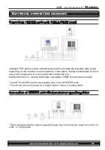
The electrical installation and connection to power supply must be done in compliance 

with the existing regulations and standards for building industry. 

• 

The fan’s engine is equipped with the internal temperature limit fuse protecting the 

engine from its overheating. 

• 

The unit set does not consist of: a feeding cable, a master switch (see diagram)

• 

The  electrical  installation  must  be  done  by  an  authorized  person,  acquainted  with 

the Manual. The connection of the feeding cable and master switch must be done in 

compliance with electrical diagram (with or without the automatic control, depending 

on the option chosen). Any and all damages incurred as a result of the aforementio-

ned causes are not provided with the Guarantee and the user will be charged with 

any costs of the device exchange. The connection of the automatic control should be 

carried out in accordance with the electrical diagram. 

• 

In case of any doubts or problems, unplug the device and contact the device’s installer 

or PAKOLE Trade Ltd. Authorized Service.

Water installation

The installation of the unit should be done in a way enabling maintenance service; on 

both stub pipes manual closing valves should be installed in order to cut off the device. 

Feeding cables of the heater shall be connected in accordance with the symbols/mar

-

king on the casing (inlet/outlet). In case of electromagnetic valve (with the option of the 

automatic control) it should be installed on the outlet as it may be damaged otherwise. 

When the pipework is being connected to the exchanger, secure the connections of the 

heater from oscillating torque (see figure) that may cause leakage in the exchanger.

Heating medium

The connector pipes are at the back of 

the device. When connecting the hydra-

ulic pipes/connections, make sure you 

secure the connector pipes against rota-

tional torque. Notice that the connector 

pipes are not strained by the pipes. The 

valve of heating medium is on the supply 

pipe and the vent is on the return pipe. 

OUT G 3/4˝

AIR WENT

IN G 3/4˝

WATER DRAIN

Summary of Contents for AIRFUSOR AFR-0

Page 1: ...tructions and notices of this Manual can cause serious bodily injuries or damages as follows burning explosion suffocation car bon monoxide poisoning electric shock and in extreme case death This appl...

Page 2: ...FURTHER INFORMATION HTTP WWW PAKOLE HU AFR WATERFAN HEATER Contents...

Page 3: ...nd basic technical parameters 8 4 Assembly 9 Electrical installation 11 Water installation 11 5 Automatomatic control installation 12ss Comfort panel description 13 First start 13 Turning off 13 Opera...

Page 4: ...e If the optional automatic control ordered it shall be delivered in a separate package Make sure all the aforementioned elements are in the package immediately after the delivery In the absence of an...

Page 5: ...tion rules supply of the necessary materials components for installation which are not be long to appliance planing of air duct systems ventilation connections service execution placing the copy of pr...

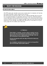
Page 6: ...cense in the field of heating and cooling installation for home and industry In any case call the Manufacturer office or the closest dealer www pakole com and ask for further informations Safety Infor...

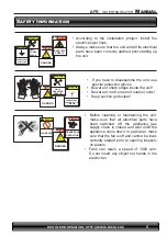
Page 7: ...Before cleaning or maintaining the unit make sure that all electrical parts have been switched off the appliance gas supply chain is closed and wait untill the appliance cools down In particular make...

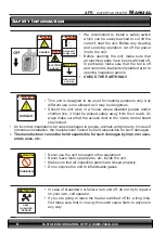
Page 8: ...leave tools spare parts etc inside the unit Make sure that all inspection panels are closed properly Do no expose the unit to inflammable gases ATTENTION FORBIDDEN In case of breakdown or failure tur...

Page 9: ...the same as the one of the ordered model Every unit is factory tested before shipment therefore if there are damages re port them immediately to the carrier Transporting unloading and moving is a pro...

Page 10: ...for vertical airflow max working range of up to 380m Horizontal range of isothermal stream at velocity boundary speed limit of 0 5 m s measurement obtained when 5 m away from the device Parametry Air...

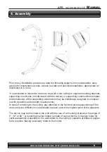
Page 11: ...ons shapes and dimensions of the supporting construction may be individually designed in complian ce with durability and strength requirements In case of mounting to the ceiling pay attention to the f...

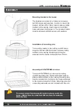
Page 12: ...nd place the bracket in The included holder must be screwed with M8 screws with washers Installation of mounting pins To mount the heater to the ceiling use M8 moun ting pins Drill two 8 9mm holes in...

Page 13: ...accordance with the electrical diagram In case of any doubts or problems unplug the device and contact the device s installer or PAKOLE Trade Ltd Authorized Service Water installation The installation...

Page 14: ...ation of 3 speeds of fan One COMFORT panel may regulate up to 3 pcs of HEATER units 2 way water valve with actuator valve should be installed on a return stub of the heater INTELLIGENT electronic cont...

Page 15: ...to air mixer HEATER MIX or for room ventilation in summer season First start Do all the connections electrical water and automatic control check for tightness of all connections done by an installer...

Page 16: ...ting fixing does not work loose contact the installer or PAKOLE Trade Ltd Authorized Service Operation The engine and fan used in HEATER units are maintenance free devices but regular check ups are ad...

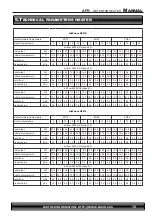
Page 17: ...ow m3 h 0 6 0 5 0 4 0 3 0 2 0 4 0 4 0 3 0 2 0 1 0 2 0 2 0 2 0 1 0 1 pressure drop kPa 0 9 0 7 0 7 0 6 0 5 0 6 0 6 0 5 0 4 0 3 0 3 0 3 0 2 0 1 0 1 AirFusor AFR 1 inlet outlet water temperature 90 70 80...

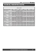
Page 18: ...1 1 1 0 0 9 0 8 0 9 0 8 0 8 0 9 0 6 pressure drop kPa 3 9 3 5 3 0 2 6 2 2 2 9 2 6 2 3 1 8 1 5 2 0 1 8 1 5 1 2 0 9 AirFusor AFR 3 inlet outlet water temperature 90 70 80 60 70 50 inlet air temperature...

Page 19: ...1 3 3 4 8 4 1 3 4 2 7 1 9 air flow 3200 m3 h speed 2 heat output kW 36 3 33 5 30 8 28 6 26 4 30 8 28 6 26 4 23 6 20 9 25 9 23 4 20 9 18 4 15 9 outlet air temperature C 36 4 37 6 40 1 43 8 47 0 30 5 33...

Page 20: ...ostat sends signal for valve actuator and fan fan turns off when tempe rature in room is achieved valve actuator closes water supply FAN function not active unit will not operate when FAN switch is se...

Page 21: ...Fans speed changs automatically for lower rate when temperature in a room gets closer to desired one Additional functions weekly thermostat availability of BMS communication signals One INTELLIGENT pa...

Page 22: ...s and valves with actuators up to 6 pcs Control of fans and valves is done using COMFORT or INTELLIGENT panel To connect more than 6 fans and valves it is possible to connect Splitter MULTI 6 with eac...

Page 23: ...ol Meaning of the symbol Switching ON OFF Programme selection Auto Cool Heat Menu button programming button Selection of fan operating mode selection of days and times Increase Decrease Screen lock He...

Page 24: ...than the required set temperature Factory settings 1 C Regulation ranges from 1 C to 10 C 02 Menu allows you to calibrate displayed room temperature 1 C tempe ratur reduction by 1 C 0 C tempera tur un...

Page 25: ...change weekend settings Repeat steps from 2 to 9 and press to confirm Notice Press to select cooling mode and repeat all of the above steps to programme cooling mode To deactivate programme 2 and 3 fo...

Page 26: ...ent use a tool specifically designated to carry out such repairs If the device has not been used for a longer period of time unplug it before the next use The heat exchanger is not equipped with any f...

Page 27: ...of parts components having construction defects that shall be delivered without any additional costs only if the defective part component has been returned 2 The Warranty for devices does not apply to...

Page 28: ...mmediately after the arrival of the Service 4 In order to make a complaint under the warranty it is necessary to deliver to the Distributor s address the following documents a a correctly filled in co...

Page 29: ...RANTY CARD INVESTMENT NAME Unit type Unit number Purchase date Startup date Installation company date Name of startup Installer Company name Address Phone Signature of startup installer Maitanance and...

Page 30: ...FURTHER INFORMATION HTTP WWW PAKOLE HU PAKOLE TRADE Ipari s Kereskedelmi Kft H 8000 Sz kesfeh rv r B rg ndi t 8 10 Honlap http www pakole hu E mail mail pakole hu Tel 36 22 316 484 Fax 36 22 316 074...

Reviews: