Section 150-431-114
Release 01
Page 5
8. ALRM MAL1: The margin on HDSL loop 1
has dropped below the minimum threshold
value set by the RS-232 terminal Margin
Alarm Threshold; as described in Section 5.
9. ALRM MAL2: The margin on HDSL loop 2
has dropped below the minimum threshold
value set by the RS-232 terminal Margin
Alarm Threshold; as described in Section 5.
4.02
The HLU-431-List 1D STATUS LED flashes
RED for the duration of a minor alarm condition.
Alarms 5 & 6 can be inhibited by selecting NONE for the
Errored Seconds Alarm (ESAL) system option. See
Section 16.03, for System Settings information. The
MAL(2) alarm can be disabled by setting the margin alarm
threshold to 0. A Minor Alarm can be retired by executing
the Alarm Cut Off (ACO) option. This is accomplished by
pressing the SEL button on the front panel. This turns the
alarm off and replaces the "ALRM" message with the
"ACO" message. The second part of the "ALRM"
message, which defines the cause of the alarm, remains.
Both messages remain until the alarm condition clears or
another alarm occurs.
4.03
Note that when both HDSL loops lose sync word
(LOSW), a minor alarm condition exists, but
because the HLU-431, List 1D enters a self test cycling
mode, the front panel LED lights yellow instead of red and
the "SELF TEST" message is displayed instead of the
"ALRM" message.
4.04
Setting the ALM option to DIS only prevents the
alarm relay from operating on a minor alarm
event. The STATUS LED still flashes red and the
"ALRM" message is still displayed.
4.05
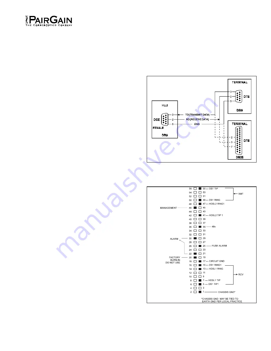
Pin 25, FUSEALARM, is driven to -48 V through
a 1000 ohm resistor and the front panel STATUS
LED turns red whenever the on-board fuse opens.
4.06
Pin 46 is the Shelf Management serial bus. It
provides access to the HMU-319 shelf controller
card which provides shelf management.
4.07
The HLU-431’s front panel tri-color Status LED
has the following states:
•
GREEN - Normal Operation
•
FLASHING GREEN - HDSL Acquisition
•
FLASHING RED - Minor Alarm (for
conditions, see Section A Paragraph 4.02)
•
RED - Fuse Alarm
•
YELLOW - Self-test in process or an HLU
Loopback in effect (CREM or NLOC)
•
FLASHING YELLOW - HLU in Armed state
Figure 3. DB-9 RS-232 I/O Pin-Outs.
A standard RS-232
(DB-9, female) connector on the front panel provides access to
the menu interface feature via a RS-232 terminal.
Figure 4. HLU-431, List 1D Card-Edge Connectors.
The
active pins are highlighted in black in the above illustration.


