


©2020 PACE Inc., Vass, North Carolina,
All Rights Reserved
Page
11
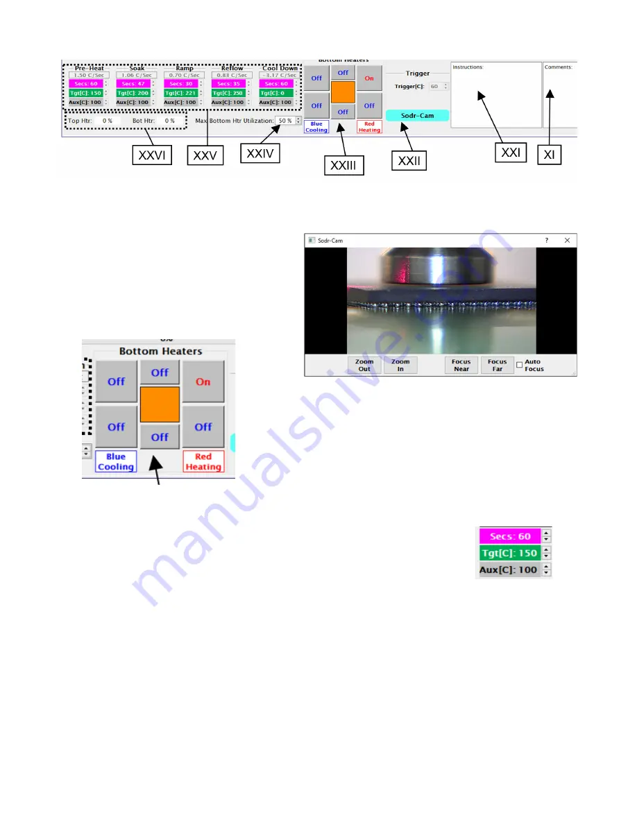
XX.
Comments
– This block can be used by the operator to record information about the production run to a
file created by the Save Production Run feature.
XXI.
Instructions
– This block will display information the Developer of the currently loaded profile left at the
profile’s creation.
XXII.
Sodr-Cam
– This button, when activated,
will bring up the viewing window for the
Sodr-Cam. Lighting for the Sodr-Cam is
adjusted using the knob on the camera.
Zoom and focus are done using the
onscreen commands.
XXIII.
Bottom Heaters –
This section will appear when using an
IR4100. The middle square will show what percentage of
power (duty cycle) the bottom heater is operating at. Each
of the surrounding squares corresponds to one of the
auxiliary heaters in the IR4100.
XXIV.
Max. Bottom Htr Utilization
– This is a limit for the
maximum power used by the bottom heater during the
profile.
XXV.
Profile Phase Indicators
– These colored blocks show the numerical values for the different aspects of
each phase of the profile and correspond to the colored indicators on the Profile Graph.
•
Magenta
– Length of time to run before moving to the next phase.
•
Green
– Target temperature for that phase of the profile.
•
Gray
– When using an IR4100, there is an additional indicator for the
auxiliary heaters.
XXVI.
Top Htr/Bot Htr
– These areas are a quick reference point of how much power the machine is applying
to the top or bottom heater elements of the machine while it is running.
XXVII.
Progress Bar
– A Visual reference indicating progress status of the process.
XXVIII.
The Profile Graph
– This chart will display real-time information about the temperature profile.


