background image

User’s Manual 


32 


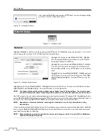
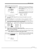
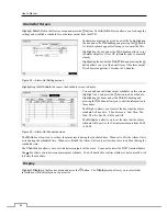
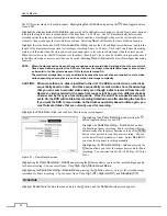
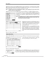
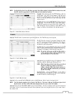
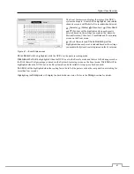
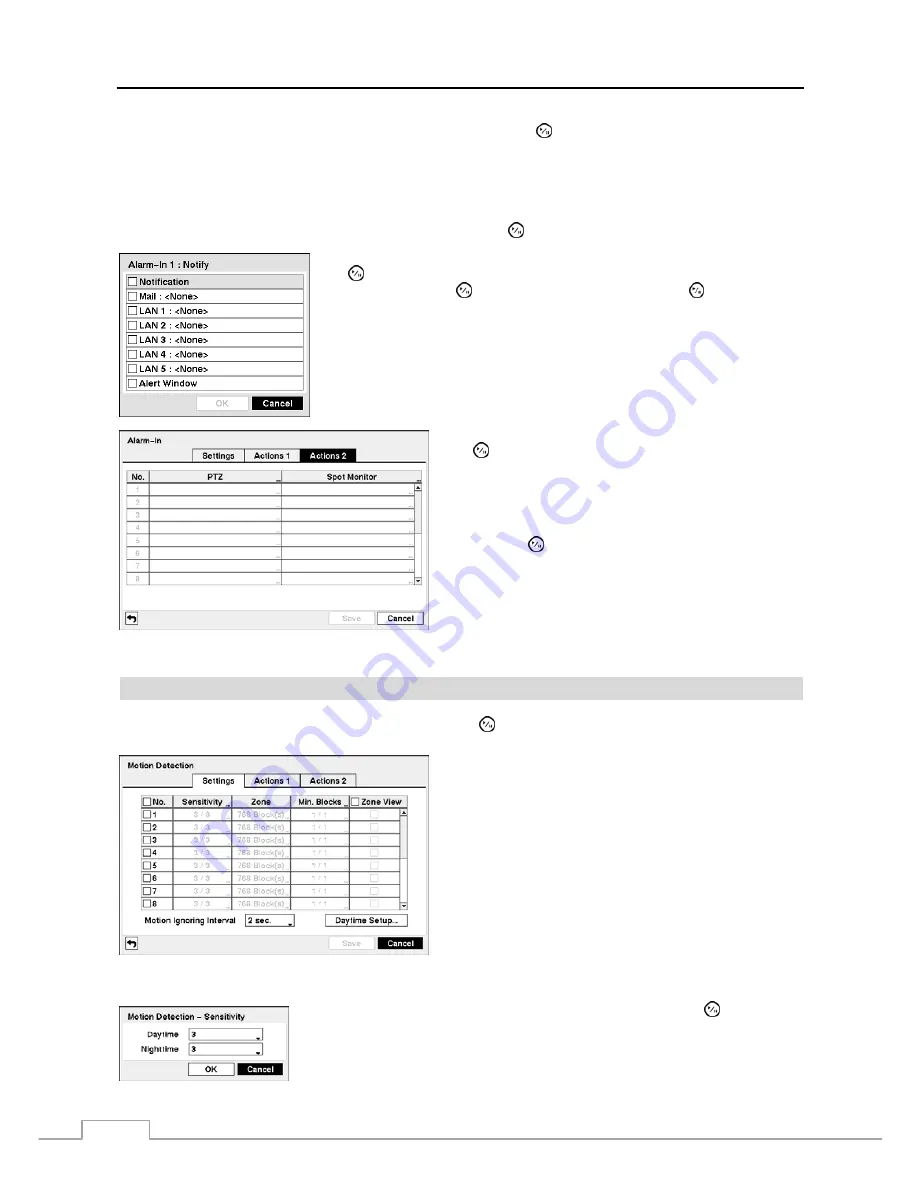
Highlight the desired box under the 

Alarm-Out 

heading, and press the   button.  A list of Alarm Outputs and Beep 

appear.  Select the Alarm Output connectors that you would like to activate whenever the DVR detects an input on the 
associated alarm input.  You can also set the DVR’s internal buzzer to sound. 


NOTE:  For the Alarm-Out action, the alarm output and beep you select should be set to the Event mode in the 

Alarm-Out setup screen (Schedule tab). 


Highlight the desired box under the 

Notify 

heading, and press the   button.  The 

Alarm-In Notify

 menu appears. 


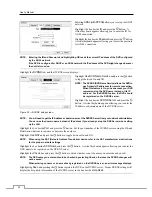
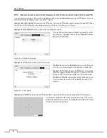
You can toggle the entire list On and Off by highlighting 

Notification

 and pressing 

the   button.  You can toggle the individual items On and Off by highlighting that 

item and pressing the   button.  Highlight 

OK

 and press the   button to accept 

your changes. 


NOTE:  For the Notify action, the notify item you select should be enabled in 

the Notification setup screen and the DVR should be registered in the 
RAS (Remote Administration System).


Highlight the desired box under the 

PTZ 

heading, and press 

the   button.  A list of PTZ presets appear.  Select the preset 

position for each PTZ camera, where you want PTZ cameras 
to move to whenever the DVR detects an input on the 
associated alarm input. 


Highlight the desired box under the 

Spot Monitor 

heading, 

and press the   button.  A list of SPOT monitors and cameras 

appears.  Each SPOT monitor can be associated with a camera.  
The DVR will display the associated camera on the SPOT 
monitor whenever it detects an input on the associated alarm 
input. 

 
Figure 44 — Alarm-In Actions 2 screen. 


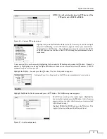
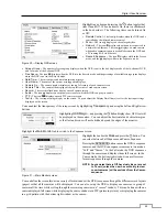
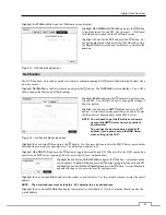
Motion Detection 


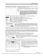
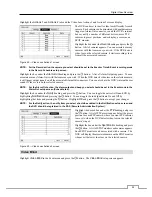
Highlight 

Motion Detection

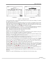
 in the Event menu and press the   button.  The Motion Detection setup screen appears.


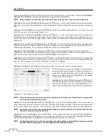
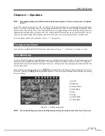
Your DVR has built-in video motion detection.  Video motion 
detection can be turned On or Off for each camera. 

 
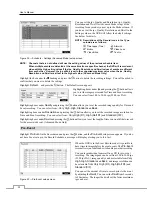
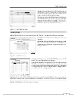
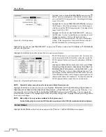
Figure 45 — Motion Detection Settings screen. 


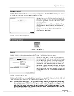
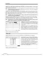
Highlighting the box under the 

Sensitivity

 heading and pressing the   button allows 

you to adjust the DVR’s sensitivity to motion for Daytime and Nighttime independently.  
There are five settings with 

1

 being the least sensitive and 

5

 being the most sensitive. 


Summary of Contents for PDRH-8-RT

Page 1: ......

Page 2: ......

Page 3: ...PROVIDE REASONABLE PROTECTION AGAINST HARMFUL INTERFERENCE WHEN THE EQUIPMENT IS OPERATED IN A COMMERCIAL ENVIRONMENT THIS EQUIPMENT GENERATES USES AND CAN RADIATE RADIO FREQUENCY ENERGY AND IF NOT IN...

Page 4: ...chnician to restore the equipment to its normal operation E If the equipment has been dropped or the cabinet damaged F When the equipment exhibits a distinct change in performance this indicates a nee...

Page 5: ...nector 5 Chapter 3 Configuration 7 Front Panel Controls 7 Camera Buttons 1 to 16 8 HDD LED 8 Alarm Out LED 8 Network LED 8 Clip Copy LED 8 Power LED 9 PANIC Button 9 ALARM Button 9 CLIP COPY Button 9...

Page 6: ...ng 43 Live Monitoring Menu 44 Active Cameo Mode 45 Zoom Mode 45 PTZ Mode 45 Event Monitoring 47 Covert Camera 47 Spot Monitoring 47 Using a Mouse 47 Recording Video 48 Panic Recording 49 Recording Aud...

Page 7: ...re 10 Date Time setup screen 14 Figure 11 Holiday setup screen 14 Figure 12 Time Sync screen 15 Figure 13 Storage Information screen 15 Figure 14 Storage Status screen 16 Figure 15 User setup screen 1...

Page 8: ...en 35 Figure 51 Video Blind Settings screen 36 Figure 52 Video Blind Actions 1 screen 36 Figure 53 Video Blind Actions 2 screen 37 Figure 54 Text In Settings screen 37 Figure 55 Text In Device screen...

Page 9: ...k drive S M A R T protocol Technical Overview In addition to replacing both a time lapse VCR and a multiplexer in a security installation your DVR has many features that make it much more powerful and...

Page 10: ...he 8 and 16 channel digital video recorders The DVRs are identical except for the number of cameras and alarms that can be connected and the number of cameras that can be displayed For simplicity the...

Page 11: ...nstall the DVR Refer to the installation manuals for the other items that make up part of your system Figure 2 16 Channel DVR rear panel Video Input Video Loop Through RS485 Port Alarm Input Output Ne...

Page 12: ...the C Common and NC Normally Closed or C and NO Normally Open connectors NC NO is a relay output which sinks 2A 125VAC and 1A 30VDC See Chapter 3 Configuration for configuring alarm output ARI Alarm...

Page 13: ...until all the LEDs on the front panel are lit NOTE When the DVR successfully resets to factory defaults all the LEDs on the front panel flash five times 5 Release the reset switch All of the DVR s set...

Page 14: ...User s Manual 6...

Page 15: ...and operates much like a VCR combined with a multiplexer Many of the buttons have multiple functions The buttons on the infrared remote control while laid out differently perform the same functions as...

Page 16: ...n 1 zooms in the screen and the button 2 zooms out the screen pressing the button 3 focuses near and button 4 focuses far and pressing the button 5 moves to the preset and button 6 saves the preset HD...

Page 17: ...TZ mode Pressing the arrow buttons or MENU CAMEO button allows you to control properly configured cameras DISPLAY SPOT Button Pressing the DISPLAY SPOT button toggles between different display formats...

Page 18: ...Pressing the button again toggles the playback speed from and The screen displays and respectively When in the pause mode pressing the button moves to the next image and pressing the button moves to...

Page 19: ...e screen Press the MENU button or move the mouse pointer to the top of the screen and then select Login in the Live Monitoring menu to enter the setup screens The Login screen appears Select a User an...

Page 20: ...n screen you can name the site location assign a System ID number select the language the screens are displayed in display software version number upgrade the software show the System Log display reco...

Page 21: ...ttings connect the USB device to the DVR Highlight Setup Export and press the button Highlight the box beside File name and press the button A virtual keyboard allows you to enter the file name Select...

Page 22: ...onds Once you have the correct time press the button Highlight the Format box beside Time and press the button Select from the three available time formats and press the button to save your selected f...

Page 23: ...vices The information in the Type column describes the storage device The capacity of the storage device is displayed in the Capacity column The Format column displays whether the device is used for r...

Page 24: ...supported NOTE When the storage condition is Bad the Event Status Storage screen displays and you can check the storage condition for details Once the Bad message displays replacing the hard disk dri...

Page 25: ...tem shutdown and logout on a local system or a PC running RAS System Time Change The user can change the system date and time on a local system or a PC running RAS Data Clear The user can clear all vi...

Page 26: ...nd press the button You can select the Resolution from High Half D1 and Standard CIF Press the button to set the Resolution NOTE The higher Quality and Resolution settings require higher Transfer Spee...

Page 27: ...ght the Port Number Setup box and press the button The Port Number Setup screen appears NOTE You will need to get the appropriate Port Numbers for each RAS and WebGuard related program Admin Callback...

Page 28: ...ddress or domain name of the DVRNS server Figure 20 DVRNS setup screen NOTE You will need to get the IP Address or domain name of the DVRNS Server from your network administrator You can use the domai...

Page 29: ...s or domain name of the SMTP server NOTE You will need to get the IP Address or domain name of the SMTP Server from your network administrator NOTE You can use the domain name instead of IP address if...

Page 30: ...igure 24 Devices menu Camera Highlight Camera in the Devices menu and press the button The Camera setup screen appears Figure 25 Camera setup screen You can turn the camera number On or Off and you ca...

Page 31: ...d pressing the button Change the number by highlighting it and using the Up and Down arrow buttons to increase and decrease the number The PTZ ID number can be set from 0 to 256 Highlight the Setup bo...

Page 32: ...hedule Highlighting the boxes under the Column heading and pressing the button allows you to edit the information in those boxes The Day box allows you to select the days that the alarm schedule will...

Page 33: ...ext input strings display on the screen You can adjust the Display Dwell time sec for the text input strings displayed on the screen You can adjust the transparency of the setup screens by highlightin...

Page 34: ...light the box in the Channels column and press the button Figure 32 Spot Monitor screen Highlight the VGA tab to switch to the VGA screen Highlight the box beside Resolution and press the button You c...

Page 35: ...e space has been used When Recycle is turned off the DVR stops recording once all available storage space has been used Highlight the Event Record Dwell box and set the length of time you would like t...

Page 36: ...e disk is installed in the unit the DVR records video on the disks sequentially based on time And these sequentially recorded videos have the advantage that you can search recorded video easily even t...

Page 37: ...lace The smallest time segment you can use is 15 minutes Highlight the box under the Mode heading and press the button to change the recording mode that will be used Choose from No Record Time Event a...

Page 38: ...recording You can select from 1 00 to 30 00 ips 25 00 ips PAL Highlighting boxes under Quality and pressing the button allows you to set the recorded image quality for Time and Event recording You can...

Page 39: ...rding whenever it senses an input on one of its alarm input connectors Highlight the box beside Panic Record and press the button A list of Alarm Inputs appears and you can select which alarm input yo...

Page 40: ...in the RAS Remote Administration System Highlight the desired box under the PTZ heading and press the button A list of PTZ presets appear Select the preset position for each PTZ camera where you want...

Page 41: ...minimum number of detection blocks for Daytime and Nighttime independently Smaller numbers provide greater sensitivity because fewer detection blocks must be activated Turning Zone View On will allow...

Page 42: ...anges NOTE For the Notify action the notify item you select should be enabled in the Notification setup screen and the DVR should be registered in the RAS Remote Administration System Highlight the de...

Page 43: ...the DVR s internal buzzer sound if video is lost on the selected camera NOTE For the Alarm Out action the alarm output and beep you select should be set to the Event mode in the Alarm Out setup scree...

Page 44: ...er an Alarm Out connector sound the DVR s internal buzzer notify a number of different devices move PTZ cameras to preset positions and or display a camera on a SPOT monitor Highlight the box under th...

Page 45: ...under the Setup heading and press the button Selecting the Setup heading changes all the parameters excluding Port settings of all the text input channels NOTE The system performance might be affecte...

Page 46: ...for the new text string The DVR will consider a transaction complete if no new text strings are entered between the last text input and the dwell time out You can adjust the Time Out dwell from 5 sec...

Page 47: ...iagnostics and report the results Highlighting the box beside System and pressing the button allows you to select the interval that you want the DVR to run self diagnostics on the system You can selec...

Page 48: ...he DVR s internal buzzer and or notify a number of different devices Highlight the Alarm Out box beside the desired event Check Recording Check Alarm In Disk Almost Full Disk Full Disk Bad Disk Temper...

Page 49: ...tected based on the settings you made in the System Event setup screen on the Event menu Panic Record will be highlighted while the DVR is in the panic recording mode Disk Almost Full will be highligh...

Page 50: ...User s Manual 42...
Page 51: ...guration Turning on the Power Once you have installed the DVR following the instructions in Chapter 2 Installation it is ready to record Live Monitoring As soon as the DVR completes its initialization...

Page 52: ...uence for the cameo sequence monitoring should be selected in the Display setup screen Main Monitor tab Camera Menu Selecting Camera Menu in the Live Monitoring menu displays the following Camera Menu...

Page 53: ...the cameo menu displayed when pressing the CAMEO button also exits the Active Cameo mode The active cameo mode will remains in effect for 15 seconds if there is no further operation In active cameo mo...

Page 54: ...pear Select the desired preset and press the button to load the preset Set Preset Move to Preset Figure 64 PTZ Preset menu While in the PTZ mode pressing the MENU button and selecting Advanced PTZ in...

Page 55: ...gs tab that camera appears to be Off unless a user with Covert Camera View authority logs into the system The camera title will be grayed out and status icons will not be displayed on the monitor NOTE...

Page 56: ...he previous or next page It is the same as pressing the GROUP button OSD Selecting OSD in the Mouse Display menu toggles OSD On and Off Recording Video Once you have installed the DVR following the in...

Page 57: ...the selected camera When in the single screen display format the camera currently displayed on the screen will be selected and when in the PIP display format the camera displayed on the PIP screen wi...

Page 58: ...OOM button zooms in the current image on the screen DISPLAY SPOT Button Pressing the DISPLAY SPOT button toggles different display formats The available formats are 2x2 3x3 and 4x4 Pressing and holdin...

Page 59: ...ill display If no video was recorded during the selected time a message appears alerting you that no image was recorded at that time The button and arrow buttons can now be used to review the surround...

Page 60: ...to live monitoring NOTE It is possible that no recorded image displays on the current screen Press the DISPLAY button and change the screen mode to 4x4 You will be able to easily see the camera have...

Page 61: ...lf diagnostic System Events as part of your search The choices are Panic Record Check Recording Check Alarm In Disk Almost Full Disk Bad Disk Temperature Disk S M A R T Fan Error Once you set your des...

Page 62: ...hing Video Go To section of this chapter for more details Clip Copy Clips a video segment and saves it see the following Clip Copy section for more details Print Prints the current playback image Zoom...

Page 63: ...d image Highlight the box beside Type and press the button You can select between Motion Search and Museum Search Motion Search detects motion in the defined area Museum Search detects if a defined ob...

Page 64: ...first recorded image Highlight the box beside To and press the button to toggle between On and Off When set to Off you can enter a specific Date and Time When set to On the search will be from the la...

Page 65: ...ill be from the first recorded image Highlight the box beside To and press the button to toggle between On and Off When set to Off you can enter a specific Date and Time When set to On the search will...

Page 66: ...le 3 individual 2GB files will be created when saving a 6GB video clip However the file size for the One Touch Clip Copy is limited to 2GB You can use other functions on the DVR while video is being b...

Page 67: ...sk drive in Windows 98 NOTE Preparing a USB hard disk drive under Windows ME is almost identical to Windows 98 1 Connect the USB hard disk drive to your computer using the USB Cable 2 Turn on your com...

Page 68: ...nt to search for Coke with a Qty Quantity of more than 1 and Hotdog with an amount totaling over 8 the following search condition can be set Search Example II 1 2 3 4 5 6 12345678901234567890123456789...

Page 69: ...tup screen WebGuard tab Or http DVRNS server address DVR name The DVRNS server address and the DVR name registered on the DVRNS server Or http www dvronline net Entering the DVR IP address or the DVR...

Page 70: ...t the Run as administrator option from the context menu Otherwise some functions of the WebGuard might be limited to use There might be a problem with screen display or screen update due to low image...

Page 71: ...he audio control panel displays click the to send audio to the connected remote site and click the button again to stop sending audio Click the to monitor live audio from the connected remote site thr...

Page 72: ...nd within the time parameters The Timetable window located at the bottom displays the time information for the image of the date selected on the calendar If more than one video stream in the same time...

Page 73: ...e In this case you can search overlapping video streams individually by selecting a specific segment For example when the DVR has recorded video from one to five o clock and the user changes the time...

Page 74: ...User s Manual 66 Map of Screens...

Page 75: ...Check camera video cable and connections Check monitor video cable and connections Confirm that the camera has power Check camera lens settings Live Video Very Bright If a cable is attached to the Loo...

Page 76: ...nt End Setup Export Cancel Print Cancel Schedule On Schedule Off Error Code Notices System Upgrade Related Clip Copy Related No Description No Description 0 Unknown error 0 Unknown error 1 File versio...

Page 77: ...System is busy clip copying Specifications VIDEO Signal Format NTSC or PAL Auto Detect Video Input Composite 8 or 16 looping inputs 1 Vp p auto terminating 75 Ohms Monitor Outputs Composite 1 BNC 1 Vp...

Page 78: ...rive or flash drive When installing an internal DVD RW drive connect the SATA I O cable to the SATA3 socket GENERAL Dimensions W x H x D 16 9 x 3 5 x 15 9 430mm x 88mm x 405mm Unit Weight 16 8 lbs 7 6...

Reviews: