packardonline.com | 800.334.1769 9
Operational Characteristics
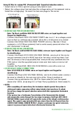
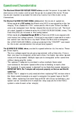
The Black and White HIGH VOLTAGE POWER wires
provide the power to operate the
electronics in the motor control and the power to operate the motor. These
inputs are required to operate the motor but cannot turn the motor on by
themselves.
The Black or Red HIGH VOLTAGE SIGNAL wires
select the mode of operation.
◦
When replacing
PSC motors
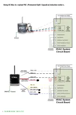
the Black wire (HV1) is energized from the fan
relay(s). This creates the “ON” command for the motor. When the Black
wire is de-energized from the fan relay(s) the motor will turn off. The level
of output (speed) is determined by the LOW VOLTAGE SIGNAL wires. The
Red wire (HV2) is not used in this configuration.
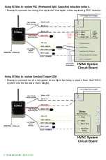
◦
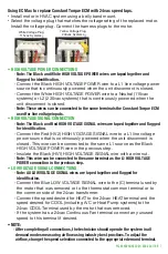
When replacing
Constant Torque ECM
the Red wire (HV2) is energized with
continuous line voltage power. This input is required to operate the motor
but cannot turn the motor on by itself. When the Red wire is energized,
the LOW VOLTAGE SIGNAL wires provide both the “ON/OFF” command
for the motor and determine the output level (speed).
The LOW VOLTAGE SIGNAL wires
provide the speed selection to the motor. These
are 24vac inputs.
◦
The low voltage signal inputs are programmed with a hierarchy. If more
than one input is energized at the same time, the higher tap value (speed
value) will be operated. Multiple taps can be energized at the same time
without damaging the motor.
◦
The optional Y-adapter is provided to allow multiple thermostat
connections to the same speed without back feeding to each other.
For example, if same speed is desired for multiple thermostat demands.
◦
IMPORTANT NOTE: The Y-adapter will only work properly on the Low and Med-Hi
speed taps.
◦
NOTE: The Y- adapter is only needed when replacing PSC motors where
the thermostat demands are used to energize the speed taps of the EC
Max. When replacing Constant Torque ECM with 24vac speed taps, any
speed can be connected to multiple fan relay outputs from the HVAC
system control board or fan relay(s).


