packardonline.com | 800.334.1769 5
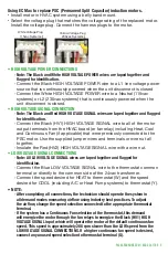
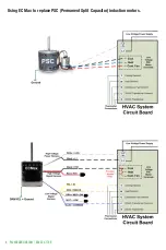
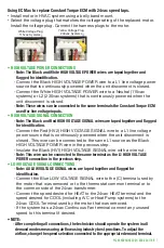
Using EC Max to replace PSC (Permanent Split Capacitor) induction motors.
• Install motor in HVAC system using a belly band mount.
• Select the voltage plug that matches the voltage rating of the replaced motor.
Install the voltage plug. Connect the harness plugs to the motor.
White Voltage Plug
115vac Systems
Yellow Voltage Plug
230vac Systems
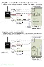
• HIGH VOLTAGE POWER CONNECTIONS
◦
Note: The Black and White HIGH VOLTAGE POWER wires are taped together and
flagged for identification.
◦
Connect the Black HIGH VOLTAGE POWER wire to a L1 line voltage power
source that is continuously powered when the unit disconnect is closed
◦
Connect the White HIGH VOLTAGE POWER wire to a Neutral (115vac
systems) or L2 (230vac systems) that is continuously powered when the
unit disconnect is closed.
• HIGH VOLTAGE SIGNAL CONNECTION
◦
Note: The Black and Red HIGH VOLTAGE SIGNAL wires are taped together and flagged
for identification.
◦
Connect the Black (HV1) HIGH VOLTAGE SIGNAL wire to all of the motor
output terminals from the HVAC board (or fan relay) including Heat, Cool
and Continuous Fan (if applicable) that were previously connected to the
PSC motor. Use the supplied jumper wires and terminals or wire nut all
together.
◦
Insulate the Red (HV2) HIGH VOLTAGE SIGNAL wire with a wire nut.
• LOW VOLTAGE SIGNAL CONNECTIONS
◦
Note: All LOW VOLTAGE SIGNAL wires are taped together and flagged for
identification.
◦
Connect the Blue LOW VOLTAGE SIGNAL wire to the thermostat common
terminal or directly to the common side of the 24vac transformer.
◦
Connect the speed desired for HEAT to thermostat (W) and the speed
desired for COOL (including A/C or Heat Pump systems) to thermostat (Y).
• NOTE:
◦
After completing all connections, the technician should operate the system in
all demand modes measuring airflow using industry best practices. To adjust
the airflow, change the speed selection connected to the appropriate thermostat
terminal.
◦
If the system has a Continuous Fan selection at the thermostat, this demand
will energize the motor through the fan relays to energize the Black (HV1) HIGH
VOLTAGE SIGNAL input which will operate the motor at the default continuous fan
speed. This speed is approximately 200 rpm slower than the LOW speed from the
LOW VOLTAGE SIGNAL CONNECTIONS. If a higher continuous fan speed is desired,
connect any unused speed selection to thermostat terminal (G).


