WARNING! For the safe operation of this machine follow
the instructions given in this booklet and the training given
by your supervisor. Failure to do so can result in personal
injury and/or damage to machine and property!
DO NOT OPERATE MACHINE IN AN EXPLOSIVE
ENVIRONMENT!
The model shown in this manual is intended for commercial
use.
PREPARATION
To prepare the machine for operation, make sure the batter-
ies are charged and the machine is properly assembled. If in
doubt, ask your supervisor.
Be prepared by having your floor area cleared and ready for
the fast action of a burnisher.
Prepare the floor area by sweeping, dusting or mopping as
needed. Check the proper application recommendations
and procedures found on the label of your finish container.
IF IN DOUBT, CALL YOUR SUPERVISOR .
WARNING! NEVER USE THIS MACHINE WITH
FLAMMABLE OR EXPLOSIVE MATERIAL!
BATTERY INSTALLATION
1. Make sure the
Toggle Switch
is in the
OFF
position.
2. Lift and remove the
Upper Hood Cover
.
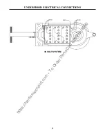
3. Place the batteries in their compartment and follow the
“Under Hood Electrical Connections”
Drawing on page 5.
BATTERY CHARGING
1. Read and follow the charger instructions.
2. Move the
Toggle Switch
to the
OFF
position.
3. Lift and remove the
Upper Hood Cover
.
4. Connect the charger plug into the mating plug on the
machine. It is located on the left side (from the operating
position) behind the batteries.
WARNING! NEVER ALLOW THE BATTERIES TO RUN
COMPLETELY DOWN,
recharge them within a few min-
utes of the
Battery Condition Meter
reading
“RECHARGE”
.
5. Plug the charger into a grounded 110 volt outlet.
WARNING! NEVER TURN THE MACHINE ON WHILE
CHARGING!
6.
After charging the batteries, disconnect the charger from
the outlet and machine.
PAD INSTALLATION
For Burnishing:
Select the correct clean floor pad (your
supplier can help you). The lighter color floor pads (buff or
white) are normally used for the burnishing procedure.
NEVER OPERATE THE MACHINE WITHOUT THE
FLOOR PAD INSTALLED!
It is very important to select clean, dry pads of uniform thick-
ness. Pads with high or low sections, or hard or soft spots
are unacceptable. Pads of open weave are recommended;
because close weaves tend to load up fast, bog down the
machines, cause circuits to overload and generally give poor
results.
1. Tilt the machine back toward the handle. The front of
the machine should be off the floor about 10-12 inches.
2. Unscrew the blue
Pad Retainer
by turning it counter-
clockwise.
3. Install or replace the pad.
4. Center the new pad on the
Pad Driver
.
4. Screw the blue
Pad Retainer
back on by turning it
clockwise. Do not over tighten.
OPERATION
1. Make sure the pad is on and attached properly. See
“Pad
Installation”.
2. Reduce the pad pressure by turning the
Caster Knob
clock-
wise.
3. Move the
Toggle Switch
to the
ON
position, the
Green
Indicator Light
will come on.
4. Check the
Battery Condition Meter
before operating. The
meter should be in the
“Working Range”
.
5. Adjust the handle to a comfortable operating position by
removing the pin on the left side of the handle, then reinsert
the pin into the nearest hole.
6. Twist the handgrips forward to operate.
7. Check the
RPM Meter
for
PROPER PAD PRESSURE:
a. With machine turned on and handgrips in the operating
position, check
RPM Meter
for pressure:
1. White area – pressure is too low.
2. Green area – pressure is good.
3. Red area – pressure is too high.
b. To adjust to desired pressure:
1. Turn
Caster knob
clockwise to raise pad and
decrease pressure.
2. Turn
Caster knob
counterclockwise to lower pad
and increase pressure.
c. For the best performance,
the
RPM Meter
should be
kept in the
“green” a
rea. A green arrow above the green
area indicates the best pressure.
NOTE: Too much pad pressure may trip the fuse.
See
“Replacing the Fuse”
on page 4.
OPERATING PROCEDURES
https://harrissupplyind.com - To Order Parts Call 608-268-8080

