


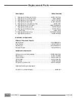


24
5055.MR30-A
180516-36
Note:
The burner tray needs to
be removed before installation or
removal of panels - See (“Burner
Tray Installation / Removal” on
page 25)
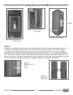
Removal
After removing the burner tray,
remove the air restrictor plate
(Figure 36) from the ceiling of
the fi rebox. This plate keeps the
side and upper back panels in
place.
1. Allow the top portion of one
side panel to move away from
the fi rebox wall (Figure 35).
When you have enough room,
remove the panel from the
stove. Repeat step 2 to remove
the second side panel.
Note: With both side panels
removed, there is nothing
holding the upper back panel
in place and so you must be
ready to support and remove
it at the same time as the
side panel.
2. Remove the upper back panel
by allowing it to tilt forward.
Remove (Figure 37).
3. Remove the lower back panel
by lifting it off of the pilot ledge
and pull it out of stove
(Figure 38).
Installation
1. Insert lower back panel so that
it is sitting on the ledge at the
back of the fi rebox (Figure 38).
2. Insert upper back panel so
that it is sitting on top of the
lower back panel as shown in
(Figure 37). The panel must be
supported until one of the side
panels is mounted in place.
Upper back
panel
Lower back
panel
Left side
panel
Right side
panel
Note: There are two tabs in
the bottom of the upper back
panel that fi t into two slots
on the top of the lower back
panel.
3. Insert fi rst side panel by tilting
the panel into the fi rebox
chamber. Then, slide the panel
until it reaches the fi rebox side
wall.
4. Repeat step 3 for the second
side panel.
5. Reinstall the air restrictor plate
6. Reinstall burner kit.
Figure 34: Interior panel set.
Figure 35: Right side panel.
Figure 36: Mirage 30 air restrictor
plate.
Figure 37: Upper back panel.
Figure 38: Lower back panel.
Firebox Panel Removal / Installation
Summary of Contents for MIRAGE 30 SERIES A
Page 33: ...33 180516 36 5055 MR30 A ...
Page 34: ...34 5055 MR30 A 180516 36 ...
Page 35: ...35 180516 36 5055 MR30 A ...


