PAC 750XL
19
accessory drives, torquemeter and propeller governor. The oil tank is integrated in the engine
air inlet casing. The oil lubricates and cools the bearings and carries extraneous matter to the
oil filter where it is precluded from further circulation. The oil is also an anti corrosion agent for
the steel bearings and gears. A chip detector is located in the reduction gear box to detect
metal particles and warn of metal contamination.
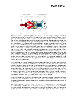
The engine air inlet is located at the front of the engine nacelle below the propeller spinner.
Ram air entering the inlet flows through ducting and an inertial separator system and then
enters the engine through a circular plenum chamber where it is directed to the compressor by
guide vanes. The compressor air inlet incorporates a screen which will prevent entry of large
articles, but does not filter the inlet air.
The inertial separator system in the engine air inlet duct prevents moisture particles from
entering the compressor air inlet plenum when in bypass mode. The inertial separator
comprises two movable vanes and a fixed airfoil which, during normal operation, route the inlet
air through a gentle turn into the compressor air inlet plenum. When separation of moisture
particles is desired, the vanes are positioned so that the inlet air is forced to execute a sharp
turn in order to enter the inlet plenum. This sharp turn causes any moisture particles to
separate from the inlet air and discharge overboard through the inertial separator outlet in the
lower cowling.
The single quadrant housing the engine controls is located in the centre of the aircraft cockpit
under the instrument panel and is accessible from the left and right seats. The power lever and
fuel condition lever control the engine and the propeller lever controls propeller speed and
feathering. The levers are provided with an adjustable friction damper and are connected by
push-pull cables to their respective engine components.
Engine indications are provided by a torque indicator, fuel computer, gas generator speed
indicator, oil temperature and pressure indicator and inter-turbine temperature indicator. The
indicators are digital with additional features such as flight timers, maximum indications held in
memory and pilot programmable warning systems.
The ignition system comprises an ignition exciter box, two high tension leads, two spark igniters,
an ignition monitor light in the annunciator panel, an ignition switch and a starter switch.
Electrical energy from the exciter box, mounted on the left engine mount truss, is transmitted via
two high tension leads to two igniters, at four and nine o’clock positions on the gas generator
case adjacent to the fuel manifold. The ignition system is normally energized only during
engine start. Ignition is controlled by one switch, located on the switch and circuit breaker
panel.
The exhaust system provides the means of ducting the jet efflux to atmosphere clear of the
engine compartment. The exhaust assembly comprises two stub pipes welded to two flanges
and the assemblies are secured to the engine exhaust flanges by 6 corrosion resistant nuts and
bolts to each assembly.
The engine starting system comprises a starter generator, a start switch, a start circuit breaker,
a starter relay, a warning light and associated wiring.


