PAC 750XL
18
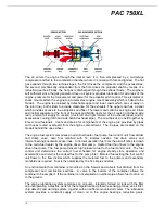
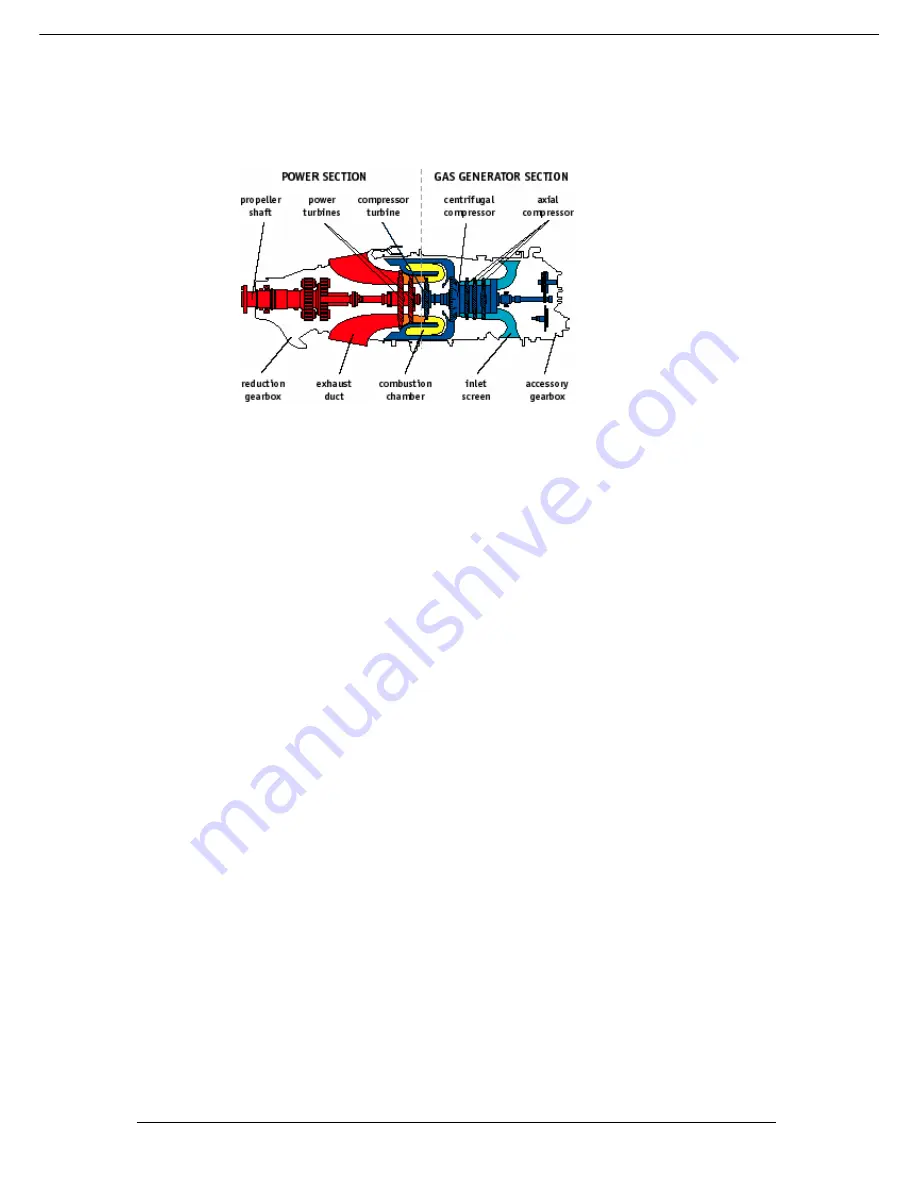
The air enters the engine through the inlet screen; it is then compressed by a multi-stage
compressor and fed to the combustion chamber where it is mixed with fuel and ignited. The hot
gas expands through two turbine stages; the first drives the compressor and the accessories;
the second, mechanically independent from the first, drives the propeller shaft by means of a
reduction gearbox. Finally, the hot gas is discharged through the exhaust ducts. The engine is
self sufficient since the gas generator driven oil system provides lubrication for all areas of the
engine, pressure for the torquemeter and power for the propeller pitch control. Three isolators or
shock mounts attach the engine to a tubular steel engine mount assembly which is bolted to the
firewall. The engine is enclosed by detachable upper and lower cowls which are cut-away on
the joint line ( both sides) to provide clearance for the exhausts. The upper cowl has a panel
which provides access to the oil dipstick and filler. The lower cowl contains an engine air intake
and inertial separator at the front of the cowl and NACA ducts for the oil cooler (right hand side
rear), ambient air supply to cockpit ( ducts left and right forward of the exhaust pipes) and for
accessories cooling (left hand side behind exhaust pipe). The cowl halves are held together by
8 lever cowl fasteners. Vents and drains for components of the engine are provided by pipes
and hoses routed overboard from the engine compartment. The 6 pipes are located on the
firewall behind the nose wheel.
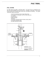
The engine fuel system comprises an oil-to-fuel heater, fuel pump, fuel control unit, flow divider
and dump valve, dual fuel manifold with 14 simplex nozzles, fuel drain valves and
interconnecting pneumatic sense lines. In normal operation fuel from the aircraft tanks is drawn
to the oil-to-fuel heater by the engine driven fuel pump. Heated fuel then flows to the engine
driven fuel pump. The fuel pump delivers high pressure fuel to the fuel control unit. The fuel
control unit determines the correct fuel schedule for engine steady state operation and
acceleration and returns the unused fuel to the pump inlet. Metered fuel exiting the fuel control
unit flows to the flow divider which supplies the metered fuel to the primary and secondary
manifolds as required. Fuel is then atomized by the 14 simplex nozzles.
An environmental fuel container is mounted on the firewall and collects fuel drained from the
compressor and combustion sections. A valve in the bottom of the container allows the
container to be emptied. If the container is not emptied an overflow pipe allows fuel to drain on
to the ground.
The engine lubrication system comprises an oil pump, integrally formed oil tank with the filler
cap incorporating a dipstick, ports for the temperature and pressure sensing probes, an oil filter,
chip detector and warning system, together with an airframe mounted oil cooler. The lubrication
system provides a constant supply of clean oil to the engine bearings, reduction gears,


