


THERMOFLO HANDPIECE
25.
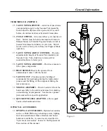
VACUUM PICK SWITCH
- Activates & deactivates
vacuum pump supply to the Vacuum Pick Assembly.
Switch must be depressed for a period of 0.5 second
before circuit deactivation; activation is immediate.
26.
CYCLE SWITCH
- Activates reflow cycle (heat & air
flow). Switch must be held to maintain activation in
Manual Mode; in Timed & Program Modes, switch is
pressed & released to initiate set cycle time. Switch
can be used to abort cycle in Timed or Program Mode
operation.
27.
VACUUM PICK ADJUST CONTROL
- Provides
adjustment for height of Vacuum Pick Assembly (&
Vacuum Cup). Turn clockwise to raise pick or
counterclockwise to lower pick.
28.
VACUUM PICK ASSEMBLY
- Provides a means to
lift or place components.
29.
HEAT SHIELD
-Protects the operator from
unintentional contact with the heater.
30.
VACUUM CUP
- Provides positive holding of
components for positioning during the replacement
process and for lifting of the component during the
removal process.
31.
NOZZLE ASSEMBLY
- Directs heated air from the
heater assembly to the solder joint areas for soldering
or desoldering of components. Nozzles are optional
parts ordered for a specific application.
32.
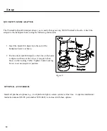
QUICKFIT NOZZLE ADAPTER
- Allows quick
nozzle attachmentand release.
OPTIONAL ACCESSORIES
33.
OPTIONAL ACCESSORIES
- Optional accessories
such as a Work Platform, preheating system, lighting
and vision attachments fume extraction and board
holders are available. Accessories are described in
"Systems & Accessories" located in the Replacement
Parts section of this manual.
Figure 3.
General Information
7
Summary of Contents for TF 200
Page 2: ...MANUAL NO 5050 0420 REV C i ...
Page 26: ...21 Quick Start ...