©2013 PACE Inc., Southern Pines, NC
Page 16 of 31
All Rights Reserved
WARNING:
The component is HOT! DO NOT remove or catch the component with bare
hands. Allow the component to drop onto the heat resistant surface. Allow
sufficient time for the component and PCB to cool to room temperature before
handling.
Component Installation; Manual Mode
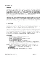
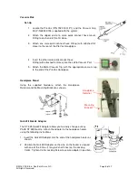
Install the proper Nozzle and Vacuum Cup (if not using Single Jet nozzle) onto the handpiece.
1. Set the unit POWER Switch (on power source front panel) to the ON
position.
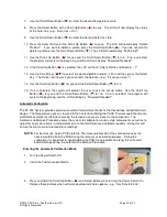
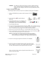
2. Use the Scroll Keys (
) to select the Manual
Mode LED.
3. Press the Menu button once. This will toggle you to
the Settings column. The LCD screen will display
the temperature and the Temp LED will be flashing.
4. Press the Select Button once.
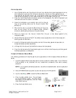
5. Now select the desired temperature with the Scroll Keys (
). Press and hold the desired
key; observe the Digital Readout as the Set Temperature increases (or decreases) in 1° and
then 10° increments as the key is held. Press the Select Button when complete.
6. Next, press the Scroll Down Button (
) once. The Blower Speed LED will now be flashing.
7. Press the Select Button and select the blower speed (1-9) by using the Scroll Keys (
).
Press the Select Button when complete to save the selections.
NOTE:
As an alternative to the component placement methods shown below in
steps 9 through 13, the component (except BGAs) may be positioned and
solder tacked in place on land pattern. See “Component Positioning Section”.
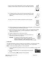
8. Actuate the vacuum by pressing the Vacuum Button on the Handpiece.
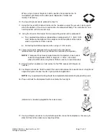
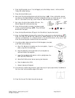
9. Position the replacement component directly beneath and square to nozzle.
When using Box or V-A-N nozzles, insert component body into the bottom of
the nozzle. BGA components will rest against the walls of the nozzle.
When using Pattern nozzles, position component leads beneath and in line
with the air jets on the nozzle.


