background image

PICO 155P Precision Saw


I

NSTRUCTION 

M

ANUAL 

- - - - - - - - - - - - - - - - - - - - - - - - - - - - - - - - - - - - - - - - - - - - - - - - - -  ▲ 

3601 E. 34th St. Tucson, AZ  85713  USA  Tel. +1 520-882-6598  Fax +1 520-882-6599  email: [email protected]    Web: http://www.metallographic.com 

40 

Please  read  this instruction  manual  carefully  and  follow  all installation,  operating  and  safety  guidelines. 
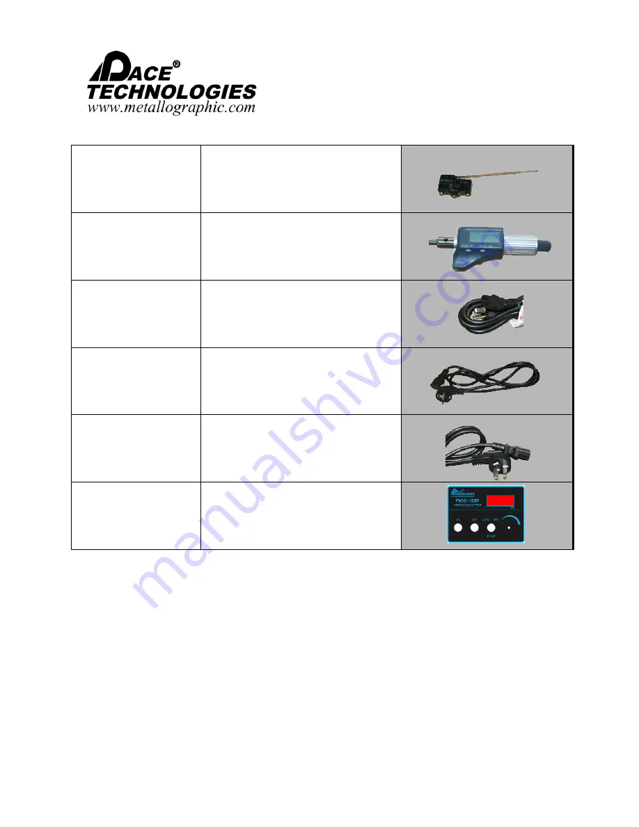


SWT-CUT-OFF 

Contact Cut-Off Switch 


P155-006 

0’’-1’’ Micrometer 


C-110V-001 

Standard 110V USA Power Cable 


C-220V-001 

220V Round Pronged Cable 


C-220V-002 

220V Flat Pronged Cable 


P155P-T 

PICO 155P Template 


Summary of Contents for PICO 155P Precision Saw

Page 1: ...graphic com Please read this instruction manual carefully and follow all installation operating and safety guidelines Equipment Type Precision Wafering Saw for 6 inch blades will accept 3 4 5 and 7 inch blades Model PICO 155P Precision Saw Electrical Requirements 110 220 Volts single phase Frequency 50 60 Hz Motor Horsepower 150 watts Manual Revision Date April 2021 ...

Page 2: ...ications and any description in catalogs circulars and other written material published by PACE Technologies is the sole purpose of identifying such goods and shall not create an express warranty that the goods shall conform to such description THIS WARRANTY IS EXPRESSLY IN LIEU OF ALL OTHER WARRANTIES EXPRESSED OR IMPLIED THERE ARE NO IMPLIED WARRANTIES OF MERCHANTABILITY OR FITNESS FOR PARTICULA...

Page 3: ...e by Buyer to pay all amounts due and payable to Seller under the work or purchase order or any other agreement between Buyer and Seller Buyer s rights under the warranty shall be suspended during any period of such default and the original warranty period will not be extended beyond its original expiration date despite such suspension of warranty rights 7 MISCELLANEOUS PROVISIONS This agreement h...

Page 4: ...read this instruction manual carefully and follow all installation operating and safety guidelines Contents PAGE Warranty i 1 0 Safety Guidelines 1 2 0 Product Description 3 3 0 Unpacking Shipping and Installation 8 4 0 Start Up and Operation 15 5 0 Maintenance 22 6 0 Troubleshooting 24 7 0 List of Spare Parts 26 8 0 Electrical and Mechanical Drawings 41 9 0 Precision Wafer Sectioning 53 ...

Page 5: ...well as improper operation voids all warranty claims All service issues need to be reported to the manufacturer supplier Before operating cutting chamber hood must be closed Use only certified wafering wheels from a professional supplier Improper blade selection voids warranty For appropriate blade selection refer to the Abrasive Blade Selection Guidelines Chart in Section 9 Disconnect power befor...

Page 6: ...op Corrective measure If cut off wheel does not power down disconnect power supply cord and call service technician 1 4 Safety Tests Emergency stop switch Emergency stop switch Test Activate main switch and close hood Depress emergency stop switch Proper Response Machine powers down Malfunction Machine does not lose power Corrective measure If system does not power down disconnect power supply cor...

Page 7: ... sectioning delicate specimens ranging from fish bones to microelectronic components It is an ideal saw for the metallographic laboratory The PICO 155P has the ability to cut at speeds ranging from 50 to 1500 rpm with loads ranging from 0 up to 1000 grams The PICO 155P is a very robust and durable precision saw with its cast aluminum alloy and stainless steel construction The PICO 155P utilizes di...

Page 8: ...monized Standards EN ISO 1200 2010 EN 61010 1 2010 EN 61326 1 2006 2 2 Technical Specifications Electrical specifications 110V 220V single phase Motor power 150 W 24V 50 60 Hz Cut off wheels 3 7 inch diameter blades Wheel arbor 0 5 inch 12 5 mm diameter Speed 50 1500 rpm Load 0 1500 grams Weight Approx 65 lbs 30 kg Dimensions WxDxH Hood closed 14 5 x 18 x 14 5 368 mm x 457 mm x 368 mm Hood open 14...

Page 9: ... USA Tel 1 520 882 6598 Fax 1 520 882 6599 email pace metallographic com Web http www metallographic com Please read this instruction manual carefully and follow all installation operating and safety guidelines 5 PICO 155P ASSEMBLY DRAWINGS Housing Casting Lid Cooling System ...

Page 10: ...afety guidelines 6 PICO 155P Precision Saw INSTRUCTION MANUAL 3601 E 34th St Tucson AZ 85713 USA Tel 1 520 882 6598 Fax 1 520 882 6599 email pace metallographic com Web http www metallographic com NOTE Assembling the counter weight rod will add 4 75 120mm in depth 19 0in 483mm 14 5in 368mm ...

Page 11: ...s Motor feedback The PICO 155P is equipped with a 125 W motor that has a feedback loop for maintaining the cutting velocity even under higher loads and increased drag In addition the circuit board has overload protection feedback which will stop the motor if the blade becomes jammed or pulls too many amps Easy to use The PICO 155P is a user friendly precision cutter with simple controls Simply ali...

Page 12: ...odily injury 3 0 Unpacking Shipping and Installation 3 1 Unpacking Unit is delivered in a box Unpack and check for completeness of parts Crate Measures WxHxD 24 x 36 x 23 Crate Weight Approximately 105 lbs 3 3 Installation Install unit carefully Improper installation voids warranty The PICO 155P should be placed on a flat stable surface Connect the micrometer by pushing the micrometer flush and th...

Page 13: ... Tank 1 Insert stainless steel tank cover tray onto coolant tank with the larger diameter hole located on the back right side of the tank Slide tank into chamber 2 Slide in the left side of the two piece stainless steel sample tray cover and then the right side cover 3 Clean and insert pump filter through both the sample tray cover and the stainless steel tank cover Insert stainless steel tank cov...

Page 14: ...guide DO NOT tighten bolts on sample support arm at this point 3 Push micrometer into the outer shaft guide thus pushing the micrometer shaft to the right While holding micrometer in place tighten set screw on outer shaft guide NOTE The hole in the micrometer does not need to line up with the bolt DO NOT over tighten the bolt as this may damage and pinch the micrometer 4 Attach sample fixture to s...

Page 15: ... E 34th St Tucson AZ 85713 USA Tel 1 520 882 6598 Fax 1 520 882 6599 email pace metallographic com Web http www metallographic com 3 3 3 Installation Weight and Counter Balance 1 Attach load arm Then snugly tighten 2 Attach counterbalance rod 3 Attach sliding counterbalance weight 4 Attach main sliding weight 5 Attach additional loading weights if desired ...

Page 16: ...com Web http www metallographic com 3 3 4 Installation flanges and blade Arbor size is 1 2 inch diameter Use largest flange as possible for more blade support Follow recommended guidelines for blade choice Attach outside flange Attach end cap and bolt Note It is recommended that the blade be dressed periodically to optimize its effectiveness Tighten bolt to secure wafering blade Adjust mechanical ...

Page 17: ...hile running saw at a slow speed Align dressing fixture with lip on front of casting panel with opening in cover Then attach the dressing fixture to the cover with the allen screws For optimum cutting performance it is recommended that the wafering blade be periodically dressed This will improve decrease cutting times as well as extend the life of the blade Note Even for hard ceramic materials dre...

Page 18: ...t or gummy materials it is recommended that the sample be positioned on the back side of the blade This will reduce the tendency of the sample to jam the blade Machine can run at either 110V or 220V power Connect the electrical plug and activate the main power switch note the hood must be closed for power to turn on at the front panel Verify that the emergency stop switch is deactivated and the sy...

Page 19: ... 2 Control Panel Digital Speed Control Cutting Wheel ON Variable Speed Controller Cutting Wheel OFF Pump AUTO MANUAL Control Emergency Shut Off Immediately cuts all power to machine Cutting wheel ON Starts the cutting wheel Cutting wheel OFF Stops the cutting wheel inductive brake engages to slow wheel Pump Control Manually controls pump ON OFF or automatically controls pump when cutting AUTO Vari...

Page 20: ...e locking bolt To prevent shaft from turning use wrench to hold in place Changing Blade Remove Loosen by turning counter clockwise Tighten Turn clockwise 4 4a Zeroing the micrometer 1 Turn micrometer on with left button 2 Press left button again and hold for several seconds until set starts to blink in the upper right hand corner of the screen 3 Press the right button several times until the numbe...

Page 21: ...e specimen during cutting A common issue with wafering saws is that the specimen can bounce or oscillate during cutting especially if the sample is positioned at the apex of the blade In this case reposition the sample generally more towards the backside of the blade is better For soft gummy materials it is recommended that the sample be positioned towards the back side of the wafering blade For t...

Page 22: ...e grit low concentration wafering blade WB 0050LC each 5 medium grit low concentration wafering blade WB 0055LC each 5 medium grit high concentration wafering blade WB 0055HC each 5 medium grit low concentration stainless steel wafering blade WB 005LCS each 5 medium grit high concentration stainless steel wafering blade WB 005HCS each 5 medium grit high concentration CBN diamond wafering blade WB ...

Page 23: ...45 each 5 CBN wafering blade WCBN 0055 each 6 CBN wafering blade WCBN 0065 each 7 inch Abrasive Blades 1 2 Arbor Pace Product Name Catalog Number Packaging per box 7 abrasive blade alumina general purpose MAX 7000S 10 pkg Wafer Cutting Fluids Pace Product Name Catalog Number Packaging per box DIACUT Oil based Cutting Fluid 16 oz OL 3000 16 16 oz DIACUT Oil based Cutting Fluid 32 oz OL 3000 32 32 o...

Page 24: ... cut 5 Remove and clean specimen after cutting 4 8 Sample Fixturing For proper clamping use the appropriate clamping vises to securely hold the sample in place It is recommended that both sides of the part be clamped to avoid pinching of the blade possibly breaking the blade and to minimize burning of the work piece during cutting For proper fixturing take into account the initial stress of the sa...

Page 25: ...com 21 Please read this instruction manual carefully and follow all installation operating and safety guidelines Universal Vice Tear Drop Vice Large Universal Vice Irregular Samples Vice Vertical Fastener Vice 32mm Round Vice 40mm Round Vice Adhering Surface Vice Double Saddle Vice All items below are included with the purchase of a PICO 155P 4 8 2 Included Sample Fixtures ...

Page 26: ...aintenance However to increase the life of the saw it is suggested that the cutting fluid be changed regularly weekly using a cutting fluid containing an anti corrosion additive e g DIACUT 2 cutting fluid After use it is also recommended that the unit be thoroughly rinsed and dried DIACUT oil based cutting fluid DIACUT 2 anti corrosion cutting fluid Remove and clean coolant tank replace with recom...

Page 27: ...w all installation operating and safety guidelines 5 2 Cleaning Outside Cabinet The cabinet and hood shield should be cleaned occasionally with a moist cloth Do not use any chemicals or cleaning abrasives We recommend an anti condensation gel be used on the front panel 5 3 Service Panel For ease of service we have designed the PICO 155P to have a side access panel with the main electrical componen...

Page 28: ...ical power supply a Verify electrical source and connection b Main power switch is off b Turn on main power switch c Emergency stop button engaged c Release by turning clockwise d Magnetic switch not engaged d Close hood or adjust hood in closed position e Shut off switch engaged e Lift specimen holder arm or adjust shut off screw to be higher f Loose or broken wire Disconnect power and open side ...

Page 29: ...de a Redress blade at 100 grams and 300 rpm b Cutting speed and or force is too low b Increase cutting speeds and applied force Excessive damage or chipping of specimen a Too large an abrasive a Use finer grit diamond blade b Excessive vibration b Secure specimen with rubber mounting pad Burr formation on specimen at the end of the cut a Cutting speed and or force is too high at the end of the cut...

Page 30: ...com 26 Please read this instruction manual carefully and follow all installation operating and safety guidelines 7 0 List of Spare Parts Part no Description Images Mechanical Components P155 M 001 Aluminum Casting P155 A AS Arbor Shaft Assembly P155 M 002 50mm Blade Arbor Flange P155 M 003 75mm Blade Arbor Flange P155 M 004 Arbor Shaft Ring P155 A BBS Blade Spacer and Bolt ...

Page 31: ...allographic com 27 Please read this instruction manual carefully and follow all installation operating and safety guidelines P155 M 005 Motor Bracket Spacer Tube P155 A COS Cut off Screw Contact Arm P155 M 006 Micrometer Shaft P155 M 007 Inner Micrometer Shaft Guide P155 M 008 Outer Micrometer Shaft Guide P155 A SSA Sample Support Arm P155 M 009 Sliding Load Arm ...

Page 32: ... Web http www metallographic com 28 Please read this instruction manual carefully and follow all installation operating and safety guidelines P155 M 010 Slighting Weight P155 M 011 Weight Rod P155 M 012 Weight 250g P155 M 013 Weight 300g P155 M 014 Counter Balance Weight P155 M 015 Counterbalance Rod P155 A PG Protractor Guide for Cutting Table ...

Page 33: ...lease read this instruction manual carefully and follow all installation operating and safety guidelines P150 701 Blade Dressing Fixture P150 702 Sample Fixture Single Universal P150 702b Sample Fixture Universal Large P150 703 Sample Fixture Double Parallel P150 706 Sample Fixture Irregular Shaped P150 707 Sample Fixture ø32mm Round Mount P150 708 Sample Fixture ø40mm Round Mount ...

Page 34: ...2 6599 email pace metallographic com Web http www metallographic com 30 Please read this instruction manual carefully and follow all installation operating and safety guidelines P150 709 Sample Fixture Adhering Surface P150 710 Sample Fixture Tear Drop 18 40mm 0 7 1 6in P150 711 Sample Fixture Fastener Fixture ...

Page 35: ...arefully and follow all installation operating and safety guidelines Part no Description Images Sheet Metal Parts P155 F 001 Front Template Backing P155 A TA Cooling Tank Assembly P155 F 002 Cooling Tank Cover Tray P155 F 003 Motor Holding Bracket P155 F 004 Steel Cutting Chamber P155 F 005 Tank guide Roller Plate P155 F 006 Electronics Base Panel P155 F 007 2 Piece Tray Cover Right P155 F 008 2 P...

Page 36: ... pace metallographic com Web http www metallographic com 32 Please read this instruction manual carefully and follow all installation operating and safety guidelines P155 F 009 Cover P155 F 010 Pump Cover P155 F 011 Cut Off Switch Cover Plate P155 F 012 Left Side Access Panel Door P155 CS A Magnetic Switch Holding Bracket ...

Page 37: ...3 Please read this instruction manual carefully and follow all installation operating and safety guidelines Part no Description Images Metalloid Parts P155 001 Power Supply Acrylic Cover P155 002 Magnetic Plastic Spacer P155 003 Acrylic Hood P155 004 Acrylic Hinge Spacers P155 005 Acrylic Dressing Fixture Cover P155 A CA Cutting Table Assembly P155 A CS Cutting Table Blade Guard ...

Page 38: ... read this instruction manual carefully and follow all installation operating and safety guidelines Part no Description Images Standard Parts P155 007 Belt Pulley P155 008 Micrometer Shaft Spring SN EX 8 Motor Spindle Snap Ring P155 009 Motor Spindle Locking Nut BB 12 28 12x28mm Bearing BB 8 16 6x16mm Bearing DB 8 10 10 Dressing Fixture Dry Bearing DB 7 5 8 Fastener Fixture Dry Bearing ...

Page 39: ... read this instruction manual carefully and follow all installation operating and safety guidelines P155 010 Hood Hinge P155 011 Hood handle P155 012 Arbor Shaft Rubber Boot P155 013 Cut Off Switch Boot P155 014 Inner Cutting Chamber Seal P155 015 Outer Cutting chamber Seal P155 016 Outer Micrometer Shaft Guide O Ring P155 017 Dual Coolant Spray Nozzles P155 P 001 Brass Reducer for Pump ...

Page 40: ...om 36 Please read this instruction manual carefully and follow all installation operating and safety guidelines PAN 18 26 18 Drip Tray M8 FEET Set of 4 Rubber Feet P155 TA C Rubber Gasket for Cooling Tank P155 018 Cooling Tank Handle P155 019 Side Panel Hinge P155 020 Cutting Table Brush P155 021 Brush for Tray Cover 1 P155 022 Brush for Tray Cover 2 P155 023 Thumb Screw M5 ...

Page 41: ...20 882 6598 Fax 1 520 882 6599 email pace metallographic com Web http www metallographic com 37 Please read this instruction manual carefully and follow all installation operating and safety guidelines TOOL 2 5 ALLEN 2 5mm Allen TOOL 4 ALLEN 4mm Allen TOOL W 14 17 14 and 17 Combo Wrench ...

Page 42: ... 38 Please read this instruction manual carefully and follow all installation operating and safety guidelines Part no Description Images Electronical Parts BTN G 001 Control Button Green BTN R 002 Control Button Red SWT E 001 Pump Switch P155 E 003 Speed Dial and Potentiometer PCB P155 Control PCB MD 24V DC Motor Controller PS 24V 24v Power Supply TB RAIL Electronics Tray Rail ...

Page 43: ...9 Please read this instruction manual carefully and follow all installation operating and safety guidelines 40MM FAN 40mm Cooling Fan PMP 24V PLD 24V Pump POW F SWITCH Electrical Switch With Fuse POW E STOP E Stop Button FUSE 3A FUSE 1 5A 3 Amp Fuse 1 5 Amp Fuse SWT MAG IN Internal Magnetic Safety Switch SWT MAG EX External Magnetic Safety Switch MOT BLDC 150 150 Watt BLDC Motor ...

Page 44: ... com Web http www metallographic com 40 Please read this instruction manual carefully and follow all installation operating and safety guidelines SWT CUT OFF Contact Cut Off Switch P155 006 0 1 Micrometer C 110V 001 Standard 110V USA Power Cable C 220V 001 220V Round Pronged Cable C 220V 002 220V Flat Pronged Cable P155P T PICO 155P Template ...

Page 45: ...ly and follow all installation operating and safety guidelines 8 0 Electrical and Mechanical Drawings ACCESS PANEL ASSEMBLY ITEM NO PART NO DESCRIPTION QTY 1 POW F SWITCH Electrical Outlet 1 2 Fuse Holder 1 3 FUSE 3A Safety Fuses 3 AMP 2 4 40MM FAN Side Panel Fan 1 5 P155 F 012 Side Access Panel 1 F1 Phillips Pan Head Screw 4mm 0 7 x 10mm 2 F2 Washer 4 5mm 2 F3 Hex Nut 4mm 0 7 2 F4 Phillips Pan He...

Page 46: ...014 Cutting Chamber and Micrometer Shaft Seal I 7 P155 016 Outer Micrometer Guide 0 Ring 1 8 P155 M 006 Micrometer Shaft 1 9 P155 008 Micrometer Shaft Spring 1 10 P155 M 008 Outer Micrometer Shaft Guide 1 11 P155 M 001 Aluminum Base Casting 1 12 M8 FEET Base Feet 4 13 P155 F 005 Tank Guide Roller 1 14 P155 A TA Stainless Steel Tank I 15 P155 018 Tank Handle 1 1 6 P155 F 002 Stainless Steel Tank Co...

Page 47: ...N QTY 1 P155P T PICO 155P Template 1 2 P155 F 001 Aluminum Template Backing 1 3 PCB P155 PICO Control PCB 1 4 BTN G 001 Green Start Button 1 s BTN R 001 Red Stop Button 1 6 SWT E 001 Auto Manual Pump Switch 1 7 Speed Control Knob 1 8 Button Locks 3 9 P155 E 003 Potentiometer 1 Fl Hex Nut 6 S mm 0 7S x 2 25mm 1 F2 Washer 7 Smm 1 F3 Slotted Set Screw 3mm O S x 2mm 1 F4 Phillips Flat Head Screw 4mm 0...

Page 48: ... r 3 2x 1 11 o 4 2x 7 ITEM NO PART NO DESCRIPTION QTY 1 P155 017 Dual Coolant Spray Nozzles 1 2 PMP 24V PLD 24V Pump PLD 2201 24V 1 3 PTC M10 E M 8MM 90 Degree Male Compression Fit ting 1 8 BS PT 8mm 2 4 P155 P 001 Hex Cap Adaptor 2 5 PTC 1 8 F 8MM Female Compression Fitting 2 6 Strainer Filter 1 7 P155 F 004 Stainless Steel Cutting Chamber 1 8 P155 F 007 8 2 Piece Stainless Steel Sample Tray Cove...

Page 49: ...4 4x ITEM NO PART NO DESCRIPTION QTY 1 MOT BLDC 150 150W BLDC Motor 1 2 P155 PCG B Motor Pulley 1 3 P155 007 Polychain Belt 1 4 P155 PCG A Blade Shaft Pulley 1 5 BB 12 28 Blade Shaft Bearing 2 6 P155 009 Locking Nut 1 7 P155 AS A Motor Shaft Bearing Housing 1 8 P155 012 Motor Shaft Rubber Boot 1 9 P155 AS B Motor Shaft 1 10 P155 BBS A Blade Spacer 1 1 1 P155 BBS B Blade Securing Bolt 1 12 P 55 M 0...

Page 50: ...Panel 1 2 POW F SWITCH Electrical Outlet 1 3 SWT MAG IN Magnetic Safety Lock Bottom 1 4 P155 F 011 Cut Off Switch Cover 1 5 P155 F 010 Pump Cover 1 6 P155 F 009 Metal Cover 1 7 P155 F 001 PICO 1 55P Front Plat e 1 8 P155P T PICO 1 55P Control Panel Template 1 9 POW E STOP Emergency St op 1 1 0 P155 019 Side Panel Hinges 2 1 1 40MM FAN Side Panel Coolant Fan 1 F1 Pan Head Bolt 4mm 0 7 x 10mm 15 F2 ...

Page 51: ...4X r4Xr4X rpsx 2X I 2X 5 F4 ITEM NO PART NO DESCRIPTION QTY l SWT MAG EX Magnetic Safely Lock Top l 2 P155 003 PICO l55P Lid l 3 P155 010 Lid Hinges Pair 2 4 P155 005 Dressing Unit Cover l 5 P155 011 Lid Handle l F1 Phillips Pan Head Screw 3mm 0 5 x 20mm 2 F2 Washer 3 5 mm 2 F3 Hex Nut 3mm 0 5 2 F4 Hex Nut 4mm 0 7 5 F5 Phillips Pan Head Screw 4mm 0 7 x 20mm 4 F6 Phillips Pan Head Screw 4mm 0 7 x l...

Page 52: ...operating and safety guidelines POWER SUPPLY ASSEMBLY F3 2x 4x 4x 5 4x F4 4 3 ITEM NO PART NO DESCRIPTION QTY 1 P155 001 Electronics Acrylic Cover 1 2 PS 24V Power Supply 1 3 MS 24V DC 24 VDC Motor Drive Controller 1 4 P155 F 006 Electronics Base Panel 1 F1 Washer 3 5mm 8 F2 Phillips Round Head Screw 3mm 0 5 x 6mm 8 F3 Phillips P an Head Screw 4mm 0 7 x 8mm 2 F 4 Bolt Adapter 3mm 0 5 x 6mm 8 F5 Ph...

Page 53: ...13 USA Tel 1 520 882 6598 Fax 1 520 882 6599 email pace metallographic com Web http www metallographic com 49 Please read this instruction manual carefully and follow all installation operating and safety guidelines FIXTURES AND ACCESSORIES a b e f i j m n c g k o d h I p ...

Page 54: ...cson AZ 85713 USA Tel 1 520 882 6598 Fax 1 520 882 6599 email pace metallographic com Web http www metallographic com 50 Please read this instruction manual carefully and follow all installation operating and safety guidelines q u y ac r s v w z aa ad ae t x ab ...

Page 55: ...mm 1 6 inch Round Specimen Vise 1 j P150 707 32mm 1 4 inch Round Specimen Vise 1 k P150 706 Specimen Vise for Irregular Shaped Samples 1 I P150 710 Teardrop Holder 18 40 mm 7 1 6 inch 1 m P150 709 Specimen Vise for Adhering Samples 1 n P150 702 Universal Holder 1 0 P155 A SSA Sample Support Arm 1 p P155 A COS Cut Off Screw 1 q P155 M 009 Sliding Load Arm 1 r P155 M 010 Sliding Load Arm Weight 1 s ...

Page 56: ...34th St Tucson AZ 85713 USA Tel 1 520 882 6598 Fax 1 520 882 6599 email pace metallographic com Web http www metallographic com 52 Please read this instruction manual carefully and follow all installation operating and safety guidelines WIRING DIAGRAM ...

Page 57: ...ristics In order to minimize cutting damage precision wafer cutting most frequently uses diamond wafering blades However for some materials the use of cubic boron nitride CBN is more efficient In addition optimal wafer cutting is accomplished by maximizing the abrasive concentration and abrasive size as well as choosing the most appropriate cutting speed and load Table III provides some general gu...

Page 58: ...n 100 Low concentration 50 Figure 9 2 Metal pressed diamond and CBN wafering blades TABLE III Precision Cutting Blade Specifications In some cases precision cutting requires a coarser grit wafering blade Usually the coarsest standard blade uses 120 grit abrasive particles For metallographic applications coarse abrasives are mostly associated with electroplated blades Figure 9 3a The main character...

Page 59: ...de right Perhaps the most important parameter for precision sectioning is the abrasive size Similar to grinding and polishing finer abrasives produce less damage For extremely brittle materials finer abrasives are required to minimize the damage produced during sectioning Sectioning with a fine abrasive wafering blade is often the only way that a specimen can be cut such that the final polished sp...

Page 60: ...t a blade s cutting performance Metal pressed wafering blades require periodic dressing in order to maintain performance A common misconception is that the cutting rates for these blades decrease because the diamond or abrasive is being pulled out of the blade In reality the metal bond is primarily smearing over the abrasive and blinding the cutting edge of the abrasive With periodic dressing usin...

Page 61: ...le 1500 500 Medium high General purpose Variable Variable Variable Medium high 9 2 Cutting Parameters Most wafer cutting is done at speeds between 50 rpm and 5000 rpm with loads varying from 10 1000 grams Generally harder specimens are cut at higher loads and speeds e g ceramics and minerals and more brittle specimens are cut at lower loads and speeds e g electronic silicon substrates see Table IV...

Page 62: ...id include Removes and suspends the cutting swarf Lubricates the blade and sample Reduces corrosion of the sample blade and cutting machine parts In general cutting fluids are either water based or oil based Figure 9 9 Water based cutting fluids are the most common because they are easier to clean However oil based cutting fluids typically provide more lubrication Figure 9 9 Oil based water based ...

Page 63: ...cutting If appropriate clamp both sides of the specimen in order to eliminate the cutting burr which can form at the end of the cut For brittle materials clamp the specimen with a rubber pad to absorb vibration from the cutting operation Begin the cut with a lower force in order to set the blade cutting kerf Orient the specimen so that it is cut through the smallest cross section For samples with ...

Reviews: