7
INSTALLATION
GENERAL REQUIREMENTS
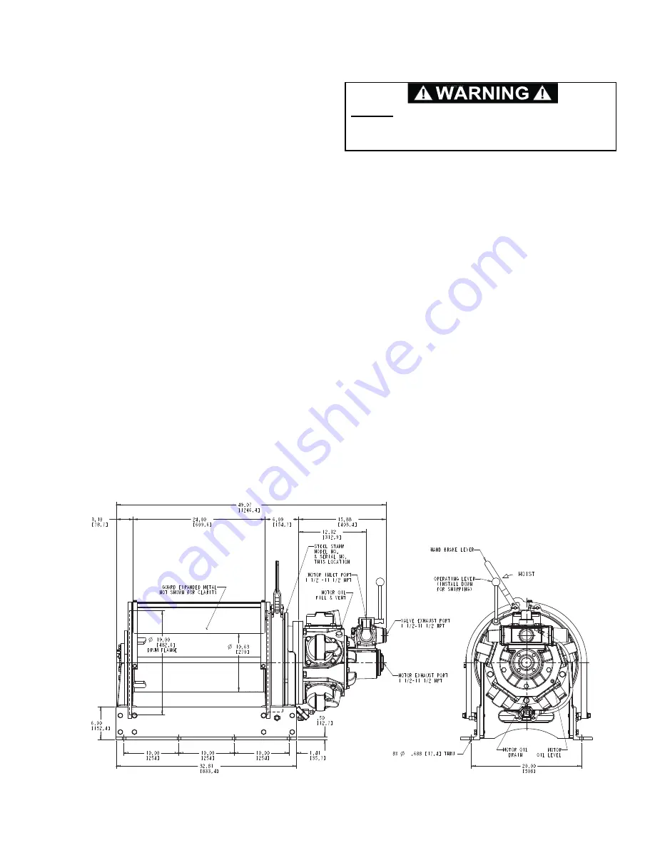
1. The hoist must be mounted with the centerline of the
drum in a horizontal position. The mounting plane can
be rotated to any position around this centerline, pro-
viding the vent plug is positioned above the oil level.
2. When mounting the winch, Grade 8, or better quality,
bolts and nuts are required. All mounting holes in the
hoist base must be used.
3. The vent plug must always be located above the hor-
izontal centerline of the hoist drum. If the hoist is
mounted on a pivoting surface, be sure the vent
remains above the centerline at all times. If neces-
sary, reposition the bearing support.
4. It is important that the hoist be mounted on a surface
that will not flex when the hoist is in use, since this
could bind the working parts of the hoist. Also, be
sure the hoist is mounted on a flat surface. If neces-
sary, use shim stock to insure proper mounting. The
mounting surface should be flat within ± 1/16 inches.
5. Make certain that the hoist drum is centered behind
the first sheave and the fleet angle does not exceed
1½ degrees. The hoist should also be mounted per-
pendicular to an imaginary line from the center of the
drum to the first sheave to ensure even spooling. (ref
page 5).
6. The air supply must be clean and free from moisture.
An airline filter and mist lubricator should be incorpo-
rated in the air supply line, located immediately
before the motor. The filter should have a moisture
trap and provide 20 micron filtration. If the rated per-
formance of the motor is to be obtained, all valves
and pipework must be of adequate size. For short
pipe runs (up to 2 meters) the supply line should be
the same size as the motor ports and larger for longer
runs. Valves should be fitted as close as possible to
the motor.
7. Before connecting to the air supply blow out the air
lines to remove any loose scale, swarf or abrasive
dust which may be present.
8. When first running the motor, some light oil should be
injected into the inlet connection to ensure adequate
lubrication until the airline lubrication is established.
9. Ensure winch and air motor crankcase have been
filled to the proper level with oil.
10. Ensure dust plugs have been removed from all air
motor ports before operating the winch.
DO NOT
install any detents or latching mechanism that
would hold the control valve in an actuated or running
position when the operator releases the control handle.
All bolts must be Grade 8 or better 5/8” with hard washer under the nut. Torque to chart specification on
Page 11.
Summary of Contents for BRADEN BA3A
Page 2: ......
Page 25: ...23 THIS PAGE INTENTIONALLY LEFT BLANK...
Page 26: ...24 WINCH CROSS SECTION...
Page 35: ...33...
Page 37: ......


