PA SDI-Drives Midi™ / Maxi™
Edition
07.44
Power Automation
2.3
Safe Restart Lock (only SDI/RL – Interface)
PA SDI-Drives Midi™ / Maxi™ in combination with the SDI/RL – Interface, supports the
safety function “safe restart lock” according to the requirements of the control category of
EN 954 Part 1 and Part 2 category 3 and ISO 13849 performance level “d”.
For this purpose, the drive has two independent safety paths in parallel connection.
The safety category is reached, when the signal ”SAFE LOCK” is additionally verified.
In addition to that, also the holding brake is part of the circuitry. The control category of
EN 954 Part 1 and Part 2 category 1 and ISO 13849 performance level “c” is reached for
the electrical circuitry of the holding brake processing. If the holding brake supply input
+24V-BR has an additional circuitry; the safety category can be increased.
2.3.1 Implementation
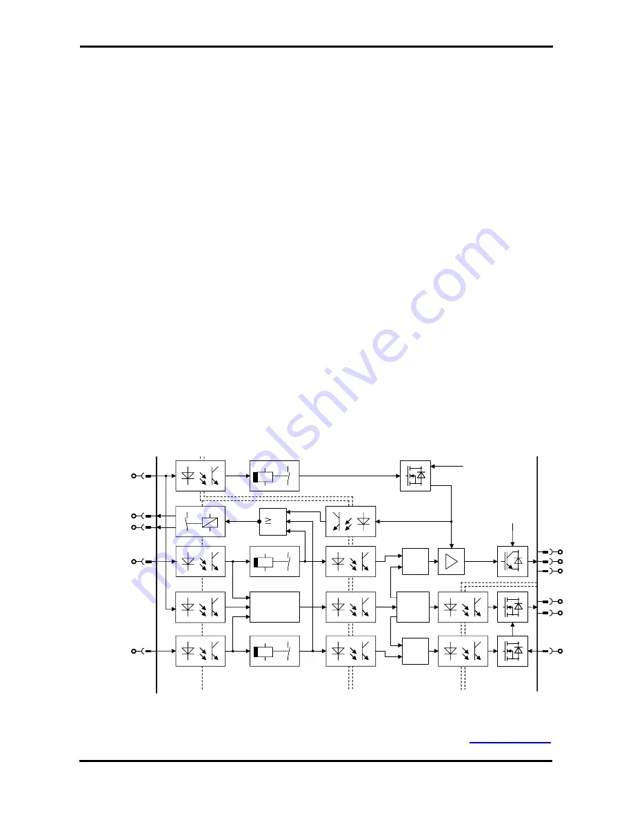
The following block diagram gives an overview over the internal circuitry.
The signals LOCK and ENABLE are directly connected to the microcontroller and also to
two independent switch-off delayed circuitries, which delay the signals in hardware for
about 0.5sec.
The delayed LOCK – signal switches off the power supply of the driver for the IGBT-power-
stage. The delayed ENABLE – signal switches off the control signals to the power stage, so
two independent signals switch off the power stage in different ways.
The signal EN-BRAKE is also galvanic isolated from the internal electronic potential by opto
coupler and is connected to a switch-off delayed circuitry, which delays the signal in
hardware for about 0.5sec. The undelayed signal is connected to the microcontroller and
the delayed signal switches off the 24V power supply of the holding brakes.
The effect of the three signals is supervised and only if all signals are in the safe state, the
relay “SAFE LOCK” closes the contact between S1 and S2.
If one or all of the signals ENABLE, LOCK or EN-BRAKE are switched off in emergency
stop condition, the drive decelerates the motors (stop category 1 according to EN 60204-1).
If all three signals are switched off, the drive is brought into the safe restart lock condition
after the delay time of 0.5sec.
Mo
tor
Low power
supply for power
stage driver
Mains power
supply
0.5s
0.5s
µ
P
1
X10
S1
S2
LOCK
EN
AB
L
E
X3, X4,
X5
Power stage potential
Electronic potential
Digital I/O
potential
U
U
V
V
W
W
11
22
55
66
&
µ
P
B+
B+
B-
B-
&
24V Aux. potential
0.5s
EN
-BR
AK
E
77
11
X1A
SAFE
Block diagram of the safe restart lock circuitry
Back to Contents
SDI Interface Manual
6


