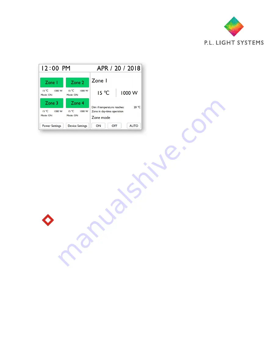
background image

Page 13

     a.  Home Screen
           i. Zone Selection Area                                                                                                                     


Navigate between Zones with arrow buttons. More detailed Zone information can be seen on  


     the right side of the screen as zones are highlighted. Press Enter to select Zone and proceed  


     to Mode Selection Area. 

          ii. Mode Selection Area


Navigate with left/right arrow buttons and press Enter to select mode  (ON/OFF/AUTO) and   


     exit Mode Selection Area.


Note: All zones are set to ON mode as the default. You will need to set them to AUTO  


             mode to operate based on programmed settings.


iii. Information Area


Navigate between Zones with arrow buttons to see more detailed information on               


     Temperature, Power and Status of a Zone. 


iv. Settings


  Navigate to Power Settings or Device Settings with arrow buttons and press Enter to proceed  


     to Power Settings screen (see page 14) or Device Settings screen (see page 16).


v. Current Date/Time


     Current date and time are displayed at the top of the home screen.

13. Screens Overview

Summary of Contents for P.L.LIGHT IQ

Page 1: ...User Manual D I G I T A L L I G H T I N G C O N T R O L L E R...

Page 2: ......

Page 3: ...rnings 6 6 Components 7 7 Accessories 7 8 Controls 8 9 Installation 9 10 Inputs 10 11 Connecting to Luminaires 10 12 Initial Setup 12 13 Screens Overview 13 14 Updating Software 17 15 Maintenance and...

Page 4: ...r is compatible with control enabled NXT LP luminaires Note NXT LP luminaire s are not included they will need to be purchased separately Key features include Digital communications protocol for more...

Page 5: ...set zone s will begin to dim 30 minutes before Lights Off Time and will turn off at Lights Off Time Dim atTemp The high temperature at which the luminaires are set to dim in order to reduce the temper...

Page 6: ...he controller if any power cord s are damaged Warning Do not expose the controller to water condensing humidity heavy mist fog or direct spray ambient temperatures outside the specified range fire exc...

Page 7: ...Light iQ and will need to be purchased separately Part Where Used Additional Interconnect Cable RJ12 RJ12 6 pin 6 position Connecting fixtures in a group One re quired for each additional fixture in g...

Page 8: ...ove down from highlighted field Left Move left from highlighted field Right Move right from highlighted field Enter Confirm highlighted selection Confirm selected value 8 Controls Highlighted Field ha...

Page 9: ...rdy solid surface 2 Holding the controller in desired location mark the position of the holes on the mounting surface using the mounting tabs on either side of the controller 3 Set controller aside an...

Page 10: ...sponding Zone 1 4 tempera ture Port B on the bottom panel of the controller and run the sensor cable the full length up to and across the ceiling if possible The sensor should be positioned as close a...

Page 11: ...ne ZONE 1 Temperature Probes T Warning When connecting the luminaire s to the controller always ensure the luminaire s is disconnected from the power source ZONE 3 ZONE 4 ZONE 2 Note Only the first RJ...

Page 12: ...t selected field Navigate between Hour Formats with left right arrow buttons and press Enter to confirm selec tion To set time navigate between Hour Minute am or pm if 12 hr format is selected with le...

Page 13: ...Selection Area Note All zones are set to ON mode as the default You will need to set them to AUTO mode to operate based on programmed settings iii Information Area Navigate between Zones with arrow b...

Page 14: ...ges to Zones Navigate between Zones with Arrow buttons Press Enter to select Zones selected zone is highlighted with gray color to which you want to apply settings above Note Zone 1 is selected by def...

Page 15: ...ter on highlighted field to setup duration with up down arrow buttons Press Enter to confirm and exit selection iii Temperature Control Option Navigate to Temperature Control ON OFF with arrow buttons...

Page 16: ...iii Time Navigate between Hour Minute am or pm if 12 hr format is selected with left right arrow buttons Press Enter on highlighted field and setup Time with up down arrow buttons Press Enter again t...

Page 17: ...or tamper with the controller in any way doing so will void the warranty For service return the controller to the place of purchase with the original sales receipt Warning Do not use acids solvents a...

Page 18: ...ted provided that the following conditions are met 1 Redistributions of source code must retain the above copyright notice this list of conditions and the following disclaimer 2 Redistributions in bin...

Page 19: ...irst line corresponds to the low level zone device Message Condition Zone mode set to always on Mode is set to ON overide ON ignore programming Zone mode set to always off Mode is set to OFF overide O...

Page 20: ...Page 20 Appendix 2 Controller Functionality Flowchart 600W minimum output power One level 25W no...

Page 21: ...The temperature sensor s should be shielded from direct exposure to the light as this may disrupt temperature readings Cut out and use hoods if necessary Appendix 3 Temperature Sensor HoodTemplate...

Page 22: ...1 800 263 0213 www pllight com 4800 Hinan Dr Beamsville ON Canada P L LIGHT SYSTEMS pl_light pllightsystems pllight pllight c pllight p l light systems PL Light iQ User Manual June 2018...

Reviews: