


F o r m X X X X : R e v i s e d 2 0 1 8
Page 3
1
Introduction
1.1
General Safety program
Accident free operation will result from a well developed, management sponsored and enforced safety
program. Of vital importance to any successful program is the proper selection of guards and devices.
However, there is no safety device that will bring “automatic” safety to your operation.
Of equal importance to this proper selection of the guard and the device is the training of your personnel.
Each person must be trained as to the operation of the guard or safety device, highlighting why they have
been provided on the equipment. Rules for safe operating should be written and enforced at all times. A final
major concern of an effective safety program is regularly scheduled inspection and maintenance of all of the
equipment.
To ensure continued safety at all times, top management, line supervision, safety engineers and all employees
must assume their proper share of the responsibility in the program. Only as a group, one that knows your
own operation and its problems, can you carry out an effective safety program.
To assist you in the development of and continued use of safety programs, many safety minded groups have
made guidelines available to you. However, you must know when and how to apply these guidelines. The
manufacturer provides information to assist you in properly adjusting and maintaining your equipment. There
is no short cut to proper safety; therefore, it is recommended that you comply with their recommendations at
all times.
1.2
Warning
This equipment offers various means of operating or controlling machines. The operator must not be in or
near the point-of-operation of the machine, or the operating parts of any equipment installed on the machine,
or bodily injury could result. The EMPLOYER must post adequate warning signs onto the machine with proper
warnings for his machine and the specific application to which the machine and equipment are being applied.
Occupational Safety and Health Act (OSHA) Sections 1910.211, 1910.212, and 1910.217 contain installation
information on the distance between danger points and point-of-operation guards and devices. No specific
references have been made to which paragraph of OSHA 1910.211, 1910.212, 1910.217 or any other
applicable sections because the paragraphs may change with each edition of the publication of OSHA
provisions. All equipment manufactured by us is designed to meet the construction standards of OSHA in
effect at the time of sale, but the EMPLOYER installs the equipment so the EMPLOYER is responsible for
installation, use, application, training, and maintenance, as well as adequate signs on the machine onto which
this equipment will be installed. Remember, OSHA says that the EMPLOYER must use operating methods
designed to control or eliminate hazards to operating personnel. It shall be the responsibility of the EMPLOYER
to establish and follow a program of periodic and regular inspections of his machine to insure that all their
parts, auxiliary equipment, and safeguards are in a safe operating condition and adjustment. Each machine
Please read this manual thoroughly before
installing, operating, applying and maintaining
this machinery. Failure to do so may result in
serious injury to yourself and/or others.
Summary of Contents for SRH10K-24
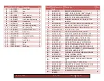
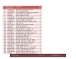
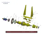
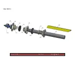
Page 15: ...F o r m X X X X R e v i s e d 2 0 1 8 Page 15 6 Parts Break Down Model SRH 10K...
Page 16: ...F o r m X X X X R e v i s e d 2 0 1 8 Page 16 Model SRH 12k...
Page 17: ...F o r m X X X X R e v i s e d 2 0 1 8 Page 17 Model SRH 15K...
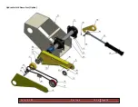
Page 18: ...F o r m X X X X R e v i s e d 2 0 1 8 Page 18 Hydraulic Hold Down Arm Option...
Page 19: ...F o r m X X X X R e v i s e d 2 0 1 8 Page 19 Hydraulic Coil Cart Option...
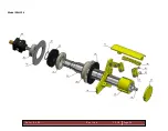
Page 20: ...F o r m X X X X R e v i s e d 2 0 1 8 Page 20 Stock Reel Body...


