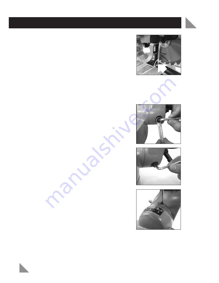
7. Place a set square (not included) on the rotating
mitre table (24) and against the flat part of the
blade (13) (Fig. 42).
NOTE:
Ensure the set square contacts the flat part of
the blade (13) and not the teeth.
8. Rotate the blade (13) by hand and check the blade-
to-table alignment at several points.
9. The edge of the set square and the blade (13)
should be parallel.
If the blade (13) angles away from the set square, adjust as follows.
10. Loosen the bevel lock lever (16) by turning in an anti-clockwise direction.
11. Use a 10mm ring spanner (not included) to loosen
the 0° bevel adjustment lock nut (Fig. 43).
12. To bring the blade (13) into alignment with the set
square adjust the 0°„ bevel adjustment screw (38)
using the 6mm allen key (15) (Fig. 44). Turning the
adjustment screw (38) in a clockwise direction will
increase the bevel angle, turning the adjustment
screw (38) in an anti-clockwise direction will
decrease the bevel angle.
13. Once the blade is aligned with the set swuare use a
Phillips Head screwdriver (not included) to loosen
the bevel angle indicator (17) (Fig. 45).
14. Adjust the position of the bevel angle indicator (17)
so that it accurately indicates zero on the bevel
index scale (18).
15. Re-tighten the screw on the bevel angle indicator (17)
by turning in a clockwise direction.
16. Re-tighten the bevel lock lever (16) and the 0° bevel adjustment lock nut.
MAINTENANCE (cont.)
23
Fig. 42
Fig.
43
Fig. 44
Fig. 45
90º


