background image

Cross Cutting (with slide action)

When cutting wide pieces of wood, ensure the slide locking knob (32) is loose. 

1. Ensure the cuttting head (3) is raised and the head locking pin (4) is released. 

2. Slide the cutting head towards you.

3. Hold the operating handle (6) firmly and turn the Mitre Saw on by depressing

the on/off switch (7). Wait for the blade (13) to reach full speed.

4. Slowly lower the cutting head (3) into the workpiece and slide it away from

you until the workpiece is cut through.

5. Release the on/off switch (7) and allow the blade (13) to stop rotating before

raising the cutting head (3) out of the workpiece. 

Bevel Cutting

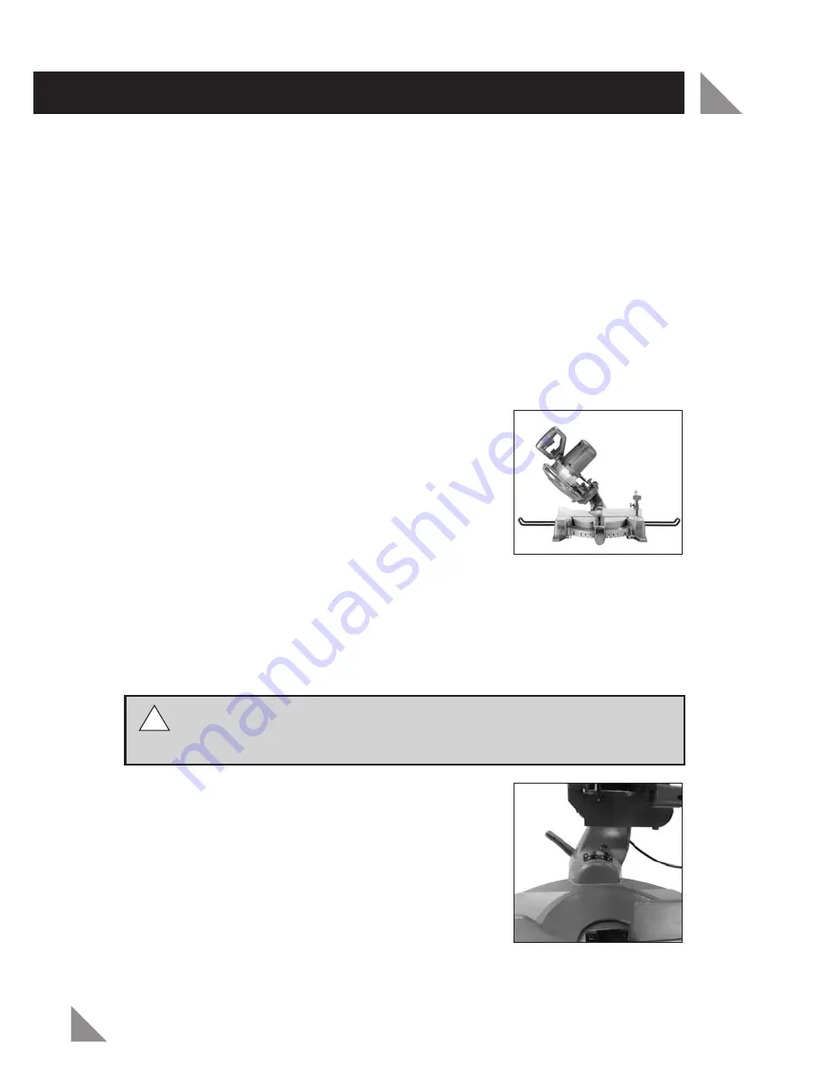
A bevel cut is made by cutting across the grain of wood
with the blade (13) angled to the rotating mitre table
(24). The mitre index scale (29) is set to 0° and the
blade (13) can be set at an angle between 1° and 45°
(Fig. 30).

When bevel cutting, the slide action is also required
when cutting wide pieces of wood.

1. Ensure the cutting head (3) is raised and the head locking pin (4) is released. 

2. Loosen the mitre lock knob (26) by turning in an anti-clockwise direction.

3. Push down on the mitre adjustment lever (27) and rotate the mitre table until

the pointer aligns with 0° on the mitre scale.

4. Retighten the mitre lock knob (26) once the rotating mitre table (24) is set at 0°.

WARNING!

Ensure the mitre lock knob (26) is tight before making a cut.

Failure to do so may result in the rotating mitre table (24) moving during
operation and cause serious personal injury. 

5. Loosen the bevel lock lever (16) and move the

cutting head (3) to the left to the desired bevel
angle (as shown on the bevel angle indicator (17))
(Fig. 31).

6. Place the workpiece flat on the rotating mitre table

(24) with one edge securely against the rear fence
(19). If the workpiece is warped, ensure the convex
side is against the rear fence (19).

OPERATION (cont.)

17

Fig. 30

Fig. 31

!!


Summary of Contents for SCMS-107

Page 1: ...y SCMS 107 WARNING Read all safety warnings and all instructions Failure to follow the warnings and instructions may result in electric shock fire and or serious injury Save all warnings and instructi...

Page 2: ...ELECTRICAL SAFETY GENERAL SAFETY INSTRUCTIONS ADDITIONAL SAFETY INSTRUCTIONS FOR MITRE SAWS SET UP AND ADJUSTMENT OPERATION MAINTENANCE SPARE PARTS DESCRIPTION OF SYMBOLS WARRANTY Page 2 Page 2 Page 3...

Page 3: ...45 x 90 145 x 65mm Bevel Cut at 0 x 45 205 x 35mm Compound Mitre Cut at 45 x 45 145 x 35mm Blade Diameter 210mm 8 1 4 Bore Size 16mm Tool Weight 16kg 2 SPECIFICATIONS MODEL NO SCMS 107 PACK CONTENTS 1...

Page 4: ...ars x2 29 31 22 Side support bar locking knobs x2 23 Bench mounting holes x4 24 Rotating mitre table 25 Table insert kerf plate 26 Mitre lock knob 27 Mitre adjustment lever 28 Mitre angle indicator 29...

Page 5: ...safety precautions when operating this tool The insulation system is for added protection against injury resulting from a possible electrical insulation failure within the tool Using an Extension Lead...

Page 6: ...y adapter plugs with earthed grounded power tools Unmodified plugs and matching outlets will reduce risk of electric shock b Avoid body contact with earthed or grounded surfaces such as pipes radiator...

Page 7: ...gned b Do not use the power tool if the switch does not turn it on and off Any power tool that can not be controlled with the switch is dangerous and must be repaired c Disconnect the plug from the po...

Page 8: ...guards are in place Do not use the saw to cut metal or masonry Do not let anyone under 18 years operate this saw Ensure that the operator is adequately trained in the use adjustment and operation of t...

Page 9: ...of your dust extraction system We recommend that you always wear a dust mask when operating this saw Wear gloves when handling saw blades and rough materials Saw blades shall be carried in a holder wh...

Page 10: ...also locked in place Only lift the Mitre Saw by the carry handle 5 and rear castings Do not lift the Mitre Saw using the upper fixed blade guard 10 retractable safety guard 11 or the operating handle...

Page 11: ...n the slide locking knob 32 turn in a clockwise direction Adjusting the Mitre Angle The mitre adjustment lever 27 is used to release the rotating mitre table 24 and allows rotation to the required mit...

Page 12: ...the Bevel Angle The bevel lock lever 16 is used to lock the cutting head 3 at the required bevel angle The Mitre Saw bevel cuts from 0 to 45 to the left 1 Turn the bevel lock lever 16 in an anti cloc...

Page 13: ...he silver column of the material clamp 8 into the hole behind the rear fence 19 Fig 10 2 Secure by rotating the material clamp lock 9 in a clockwise direction Fig 11 3 Adjust the height of the materia...

Page 14: ...d hole over the dust extraction port 2 Fig 15 Release the silver prongs to secure the dust bag 1 in position Side Support Bars When working with long workpieces the side support bars 21 provide additi...

Page 15: ...ead 3 until the trenching stop adjustment screw 33 touches the trenching stop 34 Fig 21 4 To adjust the trenching depth rotate the trenching depth adjustment screw 33 Lock it in position using the tre...

Page 16: ...necessary to use the slide mechanism In these circumstances push back the cutting head 3 and ensure the slide locking knob 32 is tight to prevent the cutting head 3 from sliding A straight cut is mad...

Page 17: ...9 6 When cutting long pieces of timber support the ends of the timber with the side support bars 21 a roller stand or a work surface bench that is level with the mitre table 24 7 Use the material clam...

Page 18: ...en 1 and 45 Fig 30 When bevel cutting the slide action is also required when cutting wide pieces of wood 1 Ensure the cutting head 3 is raised and the head locking pin 4 is released 2 Loosen the mitre...

Page 19: ...before raising the cutting head 3 Compound Mitre Cut A compound mitre cut involves using a mitre angle and bevel angle at the same time Fig 32 It is used to make picture frames cut mouldings make box...

Page 20: ...ch that is level with the mitre table 24 8 Use the material clamp 8 to secure the workpiece 9 Before turning the Mitre Saw on perform a dry test run of the cutting operation to check that there are no...

Page 21: ...r damage to the Mitre Saw This will not be covered under warranty CAUTION Never use a blade that is too thick to allow the outer blade washer to engage with the flats on the spindle It will prevent th...

Page 22: ...s a left hand thread 7 Remove the blade bolt followed by the outer blade washer The blade 13 can now be removed by pulling away from the spindle 8 Fit the new blade onto the spindle ensure the inner b...

Page 23: ...to the lowest position and engage the head locking pin 4 Fig 38 The Mitre Saw should now be secured in the transport position 3 Loosen the mitre lock knob 26 by turning in an anti clockwise direction...

Page 24: ...o bring the blade 13 into alignment with the set square adjust the 0 bevel adjustment screw 38 using the 6mm allen key 15 Fig 44 Turning the adjustment screw 38 in a clockwise direction will increase...

Page 25: ...ar Fence Square with the Blade 1 Ensure the plug is disconnected from the power supply 2 Push the cutting head 3 down to the lowest position and engage the head locking pin 4 The Mitre Saw should now...

Page 26: ...28 by turning in an anti clockwise direction Fig 50 12 Adjust the mitre angle indicator 28 so that it accurately indicates the zero position on the mitre index scale 29 13 Re tighten the screw on the...

Page 27: ...use as soon as this happens They should be replaced prior to recommencing use of the Mitre Saw Carbon brushes are a wearing component of the Mitre Saw and therefore not covered under warranty Continui...

Page 28: ...able subject to availability Please contact a local Bunnings Special Orders Desk to order the required spare parts Most common spare parts listed below Spare Part Part No Fence SPSCMS107 52 Blade Bolt...

Page 29: ...sehold waste but in an environmentally friendly way Please recycle where facilities exist Check with your local council authority for recycling advice Recycling packaging reduces the need for landfill...

Page 30: ...equency use If the tool has been operated on a supply voltage other than that specified on the tool If the tool shows signs of damage or defects caused by or resulting from abuse accidents or alterati...

Reviews: