


TROUBLESHOOTING
Disconnect the welding power source from the mains supply voltage
before disassembling. Welding equipment should be regularly checked
by a qualified electrical trades person to ensure that:
• The main earth wire of the electrical installation is intact.
•
The power point for the welding power source is effectively earthed
and of adequate current rating.
•
Plugs and cord extension sockets are correctly wired.
•
Flexible cord is of the 3-core tough rubber or plastic sheathed type of
adequate rating, correctly connected and in good condition.
• Welding terminals are shrouded to prevent inadvertent contact or
short circuit.
•
The frame of the welding power source is effectively earthed.
• Welding leads and electrode holder are in good condition.
• The welding power source is clean internally, especially from metal
filing, slag, and loose material. If any parts are damaged for any
reason, replacement is recommended.
• Prior to operation, use the terminal spanner to securely tighten the
terminal knobs.
•
Cleaning the Drive Rolls
Clean the grooves in the drive rolls frequently. This can be done by
using a small wire brush. Also wipe off, or clean the grooves on the
upper drive roll. After cleaning, tighten the drive roll retaining screws.
Note:
Ozito Industries will not be responsible for any damage or
injuries caused by the repair of the tool by an unauthorised person or
by mishandling of the tool.
This product is classified as Group 2, Class A welding equipment.
• Group 2 - This product generates radio frequency energy in the
frequency range 9KHz to 400GHz.
• Class A - This product is intended for use in an industrial
environment.
Caution:
This equipment is not intended for use in
residential environments and may not provide adequate protection
to radio reception in such environments.
MAINTENANCE
EQUIPMENT CLASSIFICATION
OPERATION
8. WELDING PROPERTIES
There are a range of welding movements used in MIG welding. Generally some
form of zig-zag motion is used to ensure the arc acts against both sheets to be
welded. Below are some details that may help with the welding process.
Travel Speed
The torch should be moved along at a smooth speed that will give the size of run
required. At the same time, the wire is fed downwards to keep the correct welding
distance at all times. Excessive travel speeds lead to poor fusion and lack of
penetration. While too slow a rate of travel may damage the work piece and can
lead to burning a hole through the material.
Electricity
The electricity flows through the wire and will not leave the wire unless it is near
an earthed object.
Electricity always finds the fastest path to the earth. When the earth cable clamp
is connected to the metal work piece a direct earth connection is created back to
the welder. When the wire touches or is near the earthed work piece when the
trigger is squeezed, electricity flows through the wire, the metal work piece and
then through the earth cable straight back to the welder.
Earth Clamp
Prior to connecting the earth clamp it may be necessary to clean the surface of
the work piece using the metal brush. Attach the earth clamp firmly to the work
piece ensuring there is good metal to metal contact. Clamp it where it will not be
in the way. This clamp provides an earth connection back to the welder.
Welding Wire
There are many variables that you will need to take into account when choosing
your welding wire size and type. Below are some of the things you need to take
into account when choosing the welding wire:
• Thickness of the material to be welded
• Position and type of welding joint
•
Maximum welding capacity of your welder
• How much penetration will be required for strength
• Type of bead desired for the weld
• Whether you are using a shielding gas or not
• Type of material to be welded
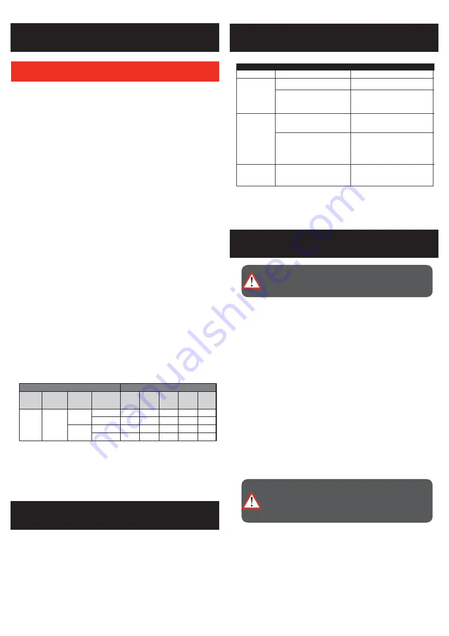
The above chart is only intended to show general guidelines for different wire
sizes and for different thicknesses of material. The settings should only be used
at the beginning of a weld and must be adjusted after stopping and carefully
inspecting the weld. Proper welding takes good technique and practice.
Flux Core Arc Welding
Material Thickness
MIG Welding
Material Thickness
Material
Being
Welded
Material
Being
Welded
Suggested
Shielding
Gas
Solid
Wire
Diameter
Suggested
Shielding
Gas
Suggested
Settings
Suggested
Settings
FCAW
Wire
Diameter
1.2mm
1.5mm 2.0mm 3.0mm 6.0mm
1.2mm
1.0mm
1.5mm 2.0mm 3.0mm 6.0mm
Steel
Steel
75% Argon
+25% CO
²
6-8L / MIN
75% Argon
+25% CO
²
8-10L / MIN
0.8
40
40
70
40
40
70
70
40
40
70
70
90
120
90
120
40
40
70
90
120
0.9
0.6
0.8
NO
GAS
Required
Current (A)
Wire Speed
Current (A)
Wire Speed
Current (A)
Wire Speed
Current (A)
Wire Speed
3~4
7~8 7.5~8 9~9.5 9.5~10
4~5
5~6
6~7
8~9
3~4
4~5
5~6
6~7
4~5
5~6
6~7
7~8
8~9
9~10
8~9
WELD SETTINGS CHART
PROBLEM
CAUSE
REMEDY
GENERAL OPERATION
No Power
Power supply
Test supply with another product, avoid using
extension leads.
Circuit breaker tripped
Check the rating of the curcuit breaker on the supply
and other appliances connected to the circuit.
The welder is a high power device and it is
recommended that is be the only appliance on the
circuit to ensure it has enough power to operate.
Welder feeding
incorectly
Wire roller wheel slipping
Increase the pressure on the pressure roller by
rotating the adjustable pressure screw in a
clockwise direction
Wire roller is applying too much pressure to
the wire
Decrease the pressure on the pressure roller by
rotating the adjustable pressure screw in an
anti-clockwise direction
Welder cuts out
Thermal overload active
The thermal overload light on the front panel will
be on and the welder will not operate until cooled
down and the light goes out. This is normal in heavy
welding, allow the welder to cool down.
WARNING:
THERE ARE EXTREMELY DANGEROUS VOLTAGE
AND POWER LEVELS PRESENT INSIDE THIS PRODUCT. DO NOT
ATTEMPT TO OPEN OR REPAIR UNLESS YOU ARE A QUALIFIED
ELECTRICAL TRADES PERSON.
CAUTION:
DO NOT USE COMPRESSED AIR TO CLEAN THE
WELDING POWER SOURCE. COMPRESSED AIR CAN FORCE
METAL PARTICLES TO LODGE BETWEEN LIVE ELECTRICAL
PARTS AND EARTHED METAL PARTS WITHIN THE WELDING
POWER SOURCE. THIS MAY RESULT IN ARCING BETWEEN THE
PARTS AND THEIR EVENTUAL FAILURE.


