background image

User Manual -

 TBOX G2

V1

03/2017

4/24


1

2

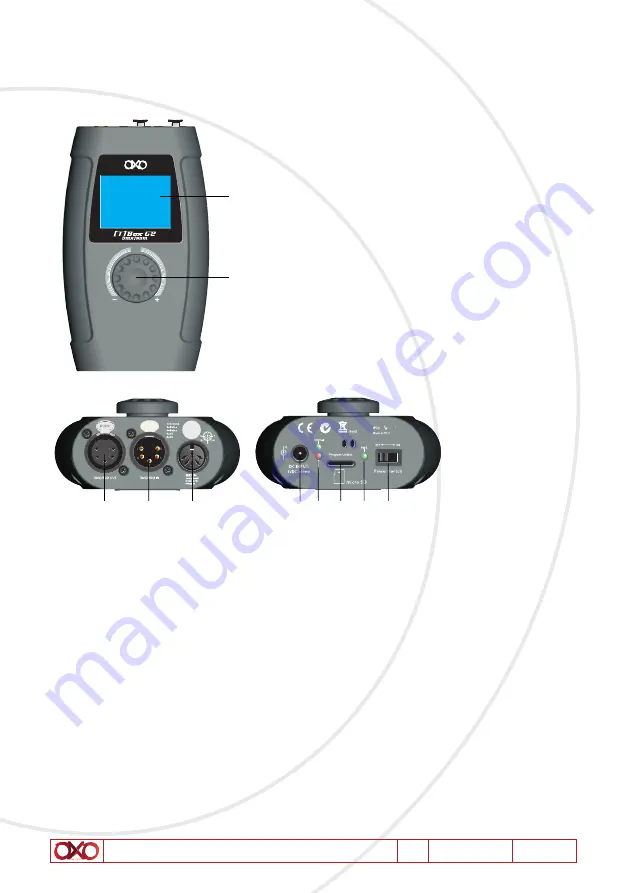
1. LCD display
2. Jog wheel
3. 9V DC power adapter IN
4. Voltage warning LED indicators
5. Micro SD slot
6. Power LED indicator
7. Power switch ON/OFF
8. 5-pin DMX/RDM signal connector OUT
9. 5-pin DMX/RDM signal connector IN
10. MIDI IN

35 C 

Under Voltage

8

9

10

3 4 5 6

7

2

6. Installation

Remove all packing materials from the TBox G2. Check if ali foam and plastic padding is remo-
ved. Connect ali cables. 
Do not supply power before the whole system is set up and connected properly. 
Always disconnect from electric mains power supply before cleaning or servicing. 
Damages caused by non-observance are not subject to warranty.

7. Set Up and Operation

Summary of Contents for T BOX G2

Page 1: ...USER INSTRUCTION T BOX G2 FOR YOUR OWN SAFETY PLEASE READ THIS USER MANUAL CAREFULLY BEFORE YOU INITIALLY START UP ...

Page 2: ... the power supply to the unit imme diately This product must be earthed Take care not to damage the power cord After having removed the packaging check that the unit is NOT damaged in any way If in doubt DON T use it and contact an authorized dealer NEVER use the unit under the following conditions In places subject to excessive humidity In places subject to vibrations or bumps In places with a te...

Page 3: ...tool for LED luminaires lt can be used to test ali the parameters and is fully compatible with DMX 512 RDM and MIDI protocols This unit can also be used as a RDM controller it can control fixtures with a RDM protocol 4 Technical specifications Power supply 9V OC 500mA power adapter Power consumption 5W Control protocols DMX 512 RDM MIDI Connections 5 pin XLR IN OUT MIDI Micro SD slot Housing PVC D...

Page 4: ...signal connector IN 10 MIDI IN 35 C Under Voltage 8 9 10 3 4 5 6 7 2 6 Installation Remove all packing materials from the TBox G2 Check if ali foam and plastic padding is remo ved Connect ali cables Do not supply power before the whole system is set up and connected properly Always disconnect from electric mains power supply before cleaning or servicing Damages caused by non observance are not sub...

Page 5: ...en your desired menu press the jog wheel to open the desired menu If you want to choose one of the submenus turn the jog wheel Press the jog wheel again to select the desired submenu The display will now show the submenu screen To return to the previous step you have to choose Exit in the submenu You can repeat steps 1 6 to navigate through all the existing menus WARNING Display Off after 30 secon...

Page 6: ...display shows DMX 512 DMX 512 Analyser DMX 512 Rx DMX 512 Tx Exit Select one of the 3 submenus DMX 512 Analyser DMX 512 Rx or DMX 512 Tx 1 1 DMX 512 Analyser Turn the jog wheel to select DMX 512 Analyser in the DMX 512 test menu Press the jog wheel to open the submenu When no signal is received the display shows DMX 512 Analyser EXIT Lost If no signal is received please check the cables and connec...

Page 7: ...u The display shows If a DMX signal is received you con see the output levels in the diagram Turn the jog wheel to select the starting channel Start Press the jog wheel to confirm and turn the jog wheel to adjust The adjustment range is between 001 512 To select a display format turn the jog wheel to select Format Press the jog wheel to enter the Format option Turn the jog wheel to select Decimal ...

Page 8: ...ode Channel level and Speed Select Channel to set which Channel a DMX signal is sent to the adjustment range is between 001 512 or Ali channels ln the option Mode you can select 4 modes Fader Only Auto ON OFF Ramping or Stop Fader Only You can change the output value by turning the jog wheel between 0 255 Auto ON OFF The output value will change automatically while adjusting the speed Ramping The ...

Page 9: ...n 0 255 Format Turn the jog wheel to change the display format choose Decimal Percents BAR RGB BRG or Hexadecimal To reset the output level of the DMX channels select Ali Reset Press the jog wheel to confirm Select Exit to return to the previous submenu Press the jog wheel to confirm Select Color Demo Mode in the DMX 512 Send submenu the displays shows ln this mode you can adjust the pixel type st...

Page 10: ...ixel Set the range between 001 512 Effect width Set the number of fixtures within the range set in Total Pixel Effect step Set the number of fixtures which switch within the range set in Effect width Test Color Set the fixture functions which you want to test Speed level Set the data speed between level 0 10 or ma nuai Fade lime Set the data fade time ratio between 0 100 Select Exit to return to t...

Page 11: ...T SET Searching Device Please wait If a fixture is not detected the display shows GET SET Found 0 RDM Device Check the power Please exit to re tryl EXIT If no fixture is detected please check the cables and connections If a fixture is detected the display shows GET SET Total Device 1 1 Device iPW 150 Para Identify Device Get Paramter Set Paramter ID 29B4 121064BD EXIT The display shows real time i...

Page 12: ...elected depends on which fixture is connected The parameters are for example lndentify Device Device lnfo DMX Start Address etc For example select the parameter lndentify Device Turn the jog wheel to select Get Parame ter or Set Parameter Select Get Parameter and press the jog wheel the display shows Select Fresh to update the info or Exit to return to the previous submenu Press the jog wheel to c...

Page 13: ...ct Ok Save to store this parameter Press the jog wheel to confirm Select Exit to return to the previous submenu Press the jog wheel to confirm To obtain info about the connected fixture select the parameter Device lnfo the display shows for example GET SET Total Device 1 1 Device iPW 150 Para Device Info Get Paramter ID 29B4 121064BD EXIT Turn the jog wheel to select Get parameter Press the jog wh...

Page 14: ...ss the jog wheel the display shows Select Fresh to update the info or Exit to return to the previous submenu Press the jog wheel to confirm Select Set Parameter and press the jog wheel the display shows Press the jog wheel to activate the DMX address Turn the jog wheel to set the DMX address Select Only Self to choose three different options Only Self Same mfrs or Ali Device Select Only self only ...

Page 15: ... store the DMX address Press the jog wheel to confirm Select Exit to return to the previous submenu Press the jog wheel to confirm Select Exit again to return to the main menu Press the jog wheel to confirm 2 2 Update RDM Oevice Note Update must be carried out by a qualified and authorized technician Turn the jog wheel to select Update RDM Oevice in the RDM main menu Press the jog wheel the displa...

Page 16: ...e device Turn the jog wheel to select Single device or Ali devices Upload the firmware file to the fixture s Select Exit to return to the previous submenu Press the jog wheel to confirm Select Exit a gain to return to the main menu Press the jog wheel to confirm 3 MIDI With this menu you con test the signal of a MIDI fixture Connect a MIDI fixture to the MIDI IN connecter 10 Turn the jog wheel to ...

Page 17: ... EXIT ACT 90 3D 64 80 3D 40 90 3A 64 80 3A 40 90 45 64 80 45 40 90 4A 64 80 4A 40 90 4C 64 80 4C 40 90 4D 64 80 4D 40 Select Exit to return to the main menu Press the jog wheel to confirm 4 Cable test With this menu you con check whether the cabling is damaged Turn the jog wheel to select CABLE Test in the main menu Press the jog wheel to open the menu The display shows ...

Page 18: ... display shows After the test you con select Try again or Exit If you select Try again the test will be repeated Select Exit to return to the main menu Press the jog wheel to confirm 5 System Setup With this menu you can set the device s settings Turn the jog wheel to select SYSTEM Setup in the main menu Press the jog wheel to open the menu The display shows And if you scroll through the setup men...

Page 19: ...t MSB Most Significant Bit Coarse first and LSB Least Significant Bit Fine first Format Select the display format Decimal Percents BAR square or Hexadecimal Contrast Level Set the contrast of the display The adjustment range is between l 0 100 from low to high contrast Backlight Off The display will turn off when no button is pressed You con set the time between 30 sec l min 2min 5min l 0min or 30...

Page 20: ... inspected by an expert after every year in the course of an acceptance test The operator has to make sure that safety related and machine technical installations are to be inspected by a skilled person once a year The electric power supply cables must not show any damages or material fatigue The TBox G2 requires almost no maintenance However you should keep the unit clean Dis connect the mains po...

Page 21: ...r the TBox G2 or light effect is at fouit Does the TBox G2 operate properly with other DMX RDM products If not take the TBox G2 in for repair If it operates properly take the DMX cable and the light effect to a qualified technician Problem Probable cause s Solution One or more fixtures do not function at all No power to the fixture Check if power is switched on and cables are plugged in Internal f...

Page 22: ...fec tive and disturbs data trans mission on the link 3 pin XLR Out on the fixtures does not match pins 2 and 3 reversed Check address setting Bypass one fixture at a time until normal opera tion is restored unplug both connectors and connect them directly together Have the defective fixture serviced by a qualified technician lnstall a phase reversing cable between the fixtures or swap pin 2 and 3 ...

Page 23: ...sumption 5W Dimensions 170 x 105 x 50 mm Weight 0 28 kg Details Onboard LCD display Contrai protocols DMX 512 RDM MIDI Connections 5 pin XLR IN OUT MIDI Micro SD slot Housing PVC Max ambient temoerature ta 35 c Max housino temperature ts 70 c Design and product specifications are subject to change without prior notice 105 mm ...

Page 24: ......

Reviews: