Microstat He Manual
9
Appendices
9.1
Electrical connections on the cryostat
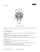
The standard cryostat is fitted with a 10-pin seal near the top of the cooling unit. This is used for the connection to the cold finger. The
seal is held in place by a black nut - do not remove it unless you need to gain access to the wiring. The heat exchanger is fitted with
a Rhodium-Iron resistance thermometer (four-wire measurement) and heater. The wiring configuration of the 10-pin seal is given in the
table below:
Pin
Function
A
Heat exchanger heater
B
Heat exchanger heater
C
Heat exchanger sensor (V+)
D
Heat exchanger sensor (V-)
E
Heat exchanger sensor (I+)
F
Heat exchanger sensor (I-)
H
Spare
J
Spare
K
Spare
L
Spare
9.1.1
Checking the wiring
A resistance meter can be used to check the wiring of the cryostat - the following readings should be expected across pins:
Pins
Nominal resistance
A - B
40 Ω approx.
C - D
30 Ω approx.
C - E
< 15 Ω
C - F
30 Ω approx.
E - F
30 Ω approx.
A - C
> 1 MΩ
A - ground
> 1 MΩ
C - ground
> 1 MΩ
9.1.2
Additional Wiring - LX10 connector
An additional 10-pin connector, fitted to the top plate of the cryostat, is wired to terminals located just above the sample holder.
© 2017 Oxford Instruments Nanoscience
MAN-MHE-1.1.0 (28ff3d8) Sep 2017
33


