


S-156-3-E
5
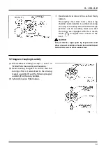
3.3 Product Code Explanation
① ② ③ ④ ⑤ ⑥ ⑦ ⑧
DESCRlPTlON
Model
N P I
Valve Position Indicator
Meter Size
4 5
Max.flowrate 8 L/min.
Pressure (meter body material) B
13.7MPa(Meter body material: FC250)
Transmitter
and Connector
0
Direct-reading type
1
Two microswitches with connector provided
2
Potentiometer provided
3
A potentiometer and two microswitches provided
9
Other than above
Connections
0
Standard (
φ
6)
1
O-ring grooved (
φ
6-P18)
2
Rc connection (Rc 3/8)
9
Other than above
3.4 General Specifications
(1) Model and Acceptable Range
Model
Flow Range, L/min (L/h)
Applicable Cylinder
Capacity (L)
NPI45
0.083 to 8 (5 to 480)
0.05 to 10
(2) Basic Body Specifications
Item
Description
Indicating Accuracy
0 to +3% (Accuracy as a flowmeter ±0.3%)
(The pointer full span at 97 to 100% of applicable cylinder capacity.)
Max. Operating Pressure
Standard type 13.7MPa
Operating Temperature Range
-10 to 80℃
Process Connection
Nominal Diameter
Specification
Connection
Standard
φ
6
O-ring grooved
Fits
φ
6-P18
Rc screw
Pc3/8
Flow Direction
Left and right. Left to right causes the pointer to move clockwise.
Acceptable Fluid
Hydraulic oil ISO VG32, 56 or equiv.
Indicator
Eccentric. Pointer deflection angle 128.3°
Finish
A single coat of primer sprayed (reddish brown)
Materials of Major Component
Parts
Pressuretight body: FC250
Rotors: Sintered Fe
Indicator housing: Plasting (polycarbonate resin)
NOTE: For explosionproof construction models, consult factory.
➡
➡


