Oval NPI45 Series Instructions Manual Download Page 15

S-156-3-E

15

(2)


Pointer Movement is unusual.

①  Inspect for possible entrapment of air.
②  If trouble is attributable to the valve position 

indicator, inspect in the same manner as in 
“Valve position indicator is dead.”

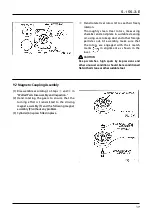
(3)   Microswitches fail to produce any signal... 

Pointer movement is all right.

①  Inspect associated equipment and field wiring 

cables for condition.

②  Taking off M3 screws (17), remove the indicator 

cover (11) (Fig. 8.11). Disconnect one end of wire 
leads from its terminal and make a continuity 
(on and off) check relative to valve opening and 
closure with multimeter (in the ohm range). If 
faulty condition persists with no signal output, 
inspect the microswitches.

③  Possible causes for the absence of signal output 

are:
(A)  An open in the internal wiring.
(B)  Microswitch positions out of adjustment.
(C)   Microswitches are defective. If this is the 

case, replace with new ones.

[See paragraph (6) in Section 9.4 Assembly 
Procedure on page 19 for adjustment.]

(4)  Potentiometer is faulty.... Pointer movement is all right.

①  Inspect related equipment and field wiring cables for condition.
②  Possible causes for trouble are:

(A)  An open or poor connections in the internal wiring.
(B)  An open in the resistor. If this is the case, replace with a new one.
[See paragraph (5) in Section 9.4 Assembly Procedure on page 19 for adjustment.]

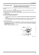
(5)  Periodic Servicing

①  It is recommended that the valve position indicator be disassembled and inspected on a regular basis 

(once every three years or so).

②  Seals, including O-rings, should be replaced with new ones each time a periodic disassembly and 

inspection is performed.

Summary of Contents for NPI45 Series

Page 1: ...you with the information pertinent to the VALVE POSITION INDICATOR With the proper application of the information and knowledge contained in this manual you will be able to expect the best possible re...

Page 2: ...10 MICROSWITCH POTENTIOMETER AND FRICTION CLUTCH ARRANGEMENTS 20 10 1 Direct reading Type and Microswitch Equipped Model 20 10 2 Potentiometer Equipped Model 20 11 ASSEMBLY DRAWINGS AND PARTS LIST 21...

Page 3: ...riods of time upon receipt before installation unexpected faulty conditions could result If a long term storage is anticipated take the following precautions 1 Keep the OVAL Valve Position Indicator i...

Page 4: ...is lightweight and compactly built OVAL Valve Position Indicator flowmeter offers electrical signal transmission to a remotely located point Features 1 Remote readout capability makes this indicator b...

Page 5: ...480 0 05 to 10 2 Basic Body Specifications Item Description Indicating Accuracy 0 to 3 Accuracy as a flowmeter 0 3 The pointer full span at 97 to 100 of applicable cylinder capacity Max Operating Pres...

Page 6: ...trical signal to a remotely located supervisory control room etc Microswitch Potentiometer Functions Transmits only the open or shut status as a contact closure signal Transmits the valve position as...

Page 7: ...l force represented by a P1 a P2 acts on rotor A forcing it to turn in the arrow direction X At a 90 displaced position then rotors A and B alternate places with each other rotor B is forced to turn i...

Page 8: ...S 156 3 E 5 MICROSWITCH POTENTIOMETER OPERATION DIAGRAMS CAUTION On specials priority is given to customer s specifications Dial Scale to Remote Indicating Signal Relationships...

Page 9: ...specified Standard polyethylene insulated cable 0 3mm2 in conductor area 2 Transmission Length The maximum signal transmission length is one kilometer NOTE If it exceeds one kilometer consult the fact...

Page 10: ...esult 3 With connector fitting screw washer and rubber packing removed pass them onto the cable pass the cable into the connector cover and pull it out toward the terminal block Rubber packing has con...

Page 11: ...ver 6 Slide the cable rubber packing and washer into the innermost part of cover and tighten cable fitting screw NOTE To avoid sag of individual conductors inside the connector cover tighten the screw...

Page 12: ...HUT or OPEN point Oval rotors continue revolving the pointer remains slipping for some time Symptoms above are indicative of excessive air or vapor in the line Bleed the line of air or vapor according...

Page 13: ...c fluid to flow in this state make sure to see that gears in the reduction gear train 12 are moving Fig 8 2 If despite a hydraulic fluid flow the reduction gear train fails to move Taking off four M3...

Page 14: ...measuring chamber for condition Fig 8 10 NOTE Each Oval rotor should be extracted in a straight line A Aren t Oval rotors jammed with foreign matter B Aren t rotors rotor shafts and other components w...

Page 15: ...absence of signal output are A An open in the internal wiring B Microswitch positions out of adjustment C Microswitches are defective If this is the case replace with new ones See paragraph 6 in Sect...

Page 16: ...d inspection reduce the pressure in the piping system completely shut off valves upstream and downstream of the indicator completely and place a suitable liquid receptacle under the indicator CAUTION...

Page 17: ...lignment as shown in the inset CAUTION Deep scratches high spots by impressions and other unusual condition should be reconditioned flat with oil stone or other suitable tool 9 2 Magnetic Coupling Ass...

Page 18: ...ar unit 12 as an assembly Inspect the gearing NOTE The reduction gear unit cannot be disassembled CAUTION 1 When separating the assembly be careful not to damage cables and conduit for field wiring 2...

Page 19: ...in mesh 4 Check the magnetic coupling for freely rotation 5 Potentiometer installation and adjustment As for the setting of resistance value see Section 5 Microswitch Potentiometer Operation Diagrams...

Page 20: ...t the pointer position is automatically corrected to the valve position 10 MICROSWITCH POTENTIOMETER FRICTION CLUTCH ARRANGEMENTS 10 1 Direct reading and Microswitch Equipped Model The friction clutch...

Page 21: ...arks 1 Body 1 2 Rotor 1 set 3 End Plate 1 4 O Ring 1 G 45 5 Driving Magnet Ass y 1 6 Cylinder 1 7 O Ring 1 G 25 8 Top Cover 1 9 Following Magnet Ass y 1 10 O Ring 1 S 63 11 Register Cover 1 12 Reducti...

Page 22: ...63 1 1 Register Cover 1 12 Reduction Gears 1 13 Friction Clutch 1 14 Dial Scale 1 15 Pointer 1 16 Bolt 6 M8 17 Screw 4 M3 18 Cap 1 19 Screw 4 M3 Sym No Part Name Q ty Remarks 20 Screw 1 M3 21 Gasket...

Page 23: ...gnet 1 10 O Ring 1 S 63 11 Register Cover 1 12 Reduction Gears 1 13 Friction Clutch 1 14 Dial Scale 1 15 Pointer 1 16 Bolt 6 M8 17 Screw 4 M3 18 Cap 1 19 Screw 4 M3 Sym No Part Name Q ty Remarks 20 Sc...

Page 24: ...Register Cover 1 12 Reduction Gears 1 13 Friction Clutch 1 14 Dial Scale 1 15 Pointer 1 16 Bolt 6 M8 17 Screw 4 M3 18 Cap 1 19 Screw 4 M3 Sym No Part Name Q ty Remarks 20 Screw 1 M3 21 Gasket 1 22 Bra...

Page 25: ...5B20 Weight 2 1kg NPI45B30 Weight 2 2kg Bottom View 4 7 G 6 6 P18 Rc 3 8 Standard terminal box location is top with respect to dial scale A model with two terminal boxes has one at left potentiometer...

Page 26: ...S 156 3 E All speci cations are subject to change for improvement 2013 01 Revised 2008 12 Revised S 156 3 E 2...

Reviews: