


S-156-3-E
3
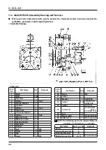
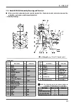
11.3 Model NPI45B20 Assembly Drawing and Parts List
● When you order replacement parts, specify product No., flowmeter model, instruction manual No.,
symbol No., part names, and the quantity desired.
◇Assembly Drawing◇
◇Parts List◇
Sym.
No.
Part Name
Q’ty
Remarks
1
Body
1
2
Rotor
1 set
3
End Plate
1
4
O-Ring
1
G-45
5
Driving Magnet
1
6
Cylinder
1
7
O-Ring
1
G-25
8
Top Cover
1
9
Following Magnet
1
10
O-Ring
1
S-63
11
Register Cover
1
12
Reduction Gears
1
13
Friction Clutch
1
14
Dial Scale
1
15
Pointer
1
16
Bolt
6
M8
17
Screw
4
M3
18
Cap
1
19
Screw
4
M3
Sym.
No.
Part Name
Q’ty
Remarks
20
Screw
1
M3
21
Gasket
1
22
Bracket
1
GSA3000
23
Gasket
1 set GSA 200-4R,
GDM 3-7R
24
Gasket
1
φ
10 I.D.
25
Connector
1
NonIS: GDM
3011J
IS: GDM 3014J
26
Potentiometer
1
CP-2FCB-1
NOTE: The following parts and subassemblies are
available as matched pair or assemblies.
Part Name
Part or Ass’y No.
Remarks
Rotors
2
Driving Magnet Ass’y
5
Following Magnet
9
Reduction Gear Ass’y
12, 13
Potentiometer incl.
➡
➡


