
67
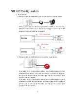
c. I/O PIN definition
• GND (Ground): Initial state is LOW
• DO (Digital Output): DC 5V
• DI (Digital Input): Max. 50mA, DC 5V
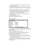
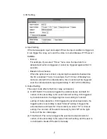
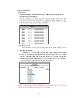
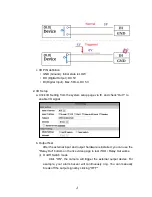
2. I/O Setup
a. Click I/O Setting from the system setup page via IE, and check “Out1” to
enable I/O signal.
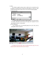
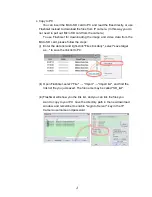
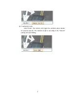
b. Output Test
After the external input and output hardware is installed, you can use the
"Relay Out" bottom on the live video page to test if DO / Relay Out works.
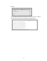
(i) OnOff Switch mode:
Click "ON", the camera will trigger the external output devise. For
example, your alarm buzzer will continuously ring. You can manually
break off the output signal by clicking "OFF".