background image


© 2022 OutdoorLink, Inc. | Updated 7.1.2022                                                                                        (256) 885-9768 | www.outdoorlinkinc.com 

SL-2-DC-002 Operating Manual 


b.


The SL-2-DC includes an integrated cellular modem to enable communication between the device and 
Outdoorlink

’s servers

 and uses LTE CAT M1 cellular technology, which is designed for IoT devices.  The 

SL-2-DC has two antenna modes 

 internal and external 

 and is configured to internal mode when 

shipped.  


It is critical that the SL-2-DC is configured for the proper antenna mode.  A user may change antenna 
mode 

by pressing the “ON/OFF 2” 

or 

“ON/OFF 1” push buttons for 5 seconds. 

 The Status LED provides 

visual confirmation of what antenna mode the SL-2-DC is set to. 


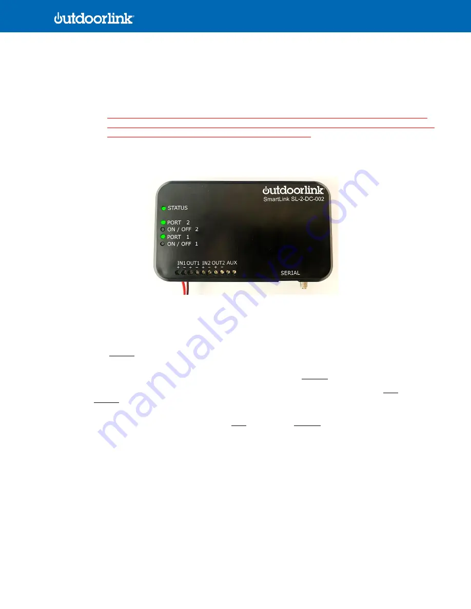
Figure 6. SL-2-DC-002 with power supply and status lights on  


STATUS LED  

1.


Slow Blink: One blink per second continuously indicates that the device is searching for the cellular network 
while in 

internal

 antenna mode. 

2.


Slow Blink with Two Second Pause: One blink per second for two seconds followed by two second pause 
indicates that the device is searching for the cellular network while in 

external

 antenna mode. 

3.


Rapid Blink: Multiple blinks per second confirms the device is connected to the cellular network 

AND

 configured 

for 

internal

 antenna mode. 

4.


Rapid Blink with One Second Pause: Rapid blink for five seconds followed by a one second pause confirms that 
the device is connected to the cellular network 

AND

 configured for 

external

 antenna mode.  

 
PORT 1 and 2 LED  

1.


A solid LED indicates Port 1,2 is powered with a load connected. 

2.


A rapid blink LED light Port 1,2 is powered without a load connected. 

3.


No LED indicates Port 1,2 is not powered. 

 
ON/OFF 1 and 2  

1.


Push button to toggle Port 1,2 to ON or OFF position.  


Summary of Contents for SmartLink SL-2-DC-002

Page 1: ...ing the installation of SmartLink controllers and assumes no liability for injury or death incurred during the process Questions Contact OutdoorLink s support team at 256 885 9768 ext 1 or support outdoorlinkinc com Table of Contents 2 Product Overview 3 Controller Interface 4 Hardware Specifications 5 Split Power Supply Wiring Diagram 6 Single Power Supply Wiring Diagram 7 Installation Guidelines...

Page 2: ...g and Real time Displays IT and Networking Lighting Systems Solar Systems SmartLink controllers are hardwired to devices in the field and communicate through an independent Machine to Machine cellular connection From there data passes through Outdoorlink s AWS server and is available to users in the SmartLink portal through cellular or internet access Every SmartLink controller can be accessed fro...

Page 3: ...y status 2 PORT 2 Confirmation that power is passing through to Port 2 3 ON OFF 2 Manual push button to turn port 2 on or off 4 PORT 1 Confirmation that power is passing through to Port 2 5 ON OFF 1 Manual push button to turn port 1 on or off 6 IN1 DC power IN to Port Device 1 7 OUT1 DC power OUT to Port Device 1 8 IN2 DC power IN to Port Device 2 9 OUT2 DC power OUT to Port Device 2 10 AUX Auxili...

Page 4: ...ial Black polycarbonate ABS UL94 Dimensions 5 82 L x 3 60 W x 0 95 H Input Voltage 4A max 5 30Vdc per relay Output Voltage 4A max 5 30Vdc per relay Power Consumption 0 15 W or 0 01 A Connectivity LTE Cat M1 with integrated antenna with external antenna option Smart Weather Devices activate outside of scheduled run times per NOAA forecast maps Operating Temp 0 C to 65 C Environmental 0 95 humidity ...

Page 5: ...wo devices operating at different voltages such as a 12V supply and a 12V device can be placed on one input and output while a 19V supply and device can be placed on the other This configuration is common for installations with 12V LEDs 12V WIFI routers 12V Digital Displays 12V 19V Media Players Kiosks and Digital Advertising Figure 4 Wiring diagram for split power supply DC INPUT 2 DC OUTPUT 1 ma...

Page 6: ... at the same voltage using a single DC input For example a 12V supply can power two separate 12V devices in this configuration and a jumper wire is used to connect the IN1 and IN2 This configuration is common for installations including 12V LEDs 12V WIFI routers 12V Digital Displays 12V Media Players Solar Packages Figure 5 Wiring diagram for single power supply 18 AWG Jumper Wire Connects IN to I...

Page 7: ...ward for optimal cellular connectivity Locate the SL 2 DC controller away from direct sunlight 2 Place the SmartLink on the chosen location and use double sided tape or Velcro to secure the unit 3 The SL 2 DC controller requires 18 AWG wiring for both input and output connections For devices with barrel jack connectors OutdoorLink can provide a Connector Kit with female and male barrel connectors ...

Page 8: ...ow Blink One blink per second continuously indicates that the device is searching for the cellular network while in internal antenna mode 2 Slow Blink with Two Second Pause One blink per second for two seconds followed by two second pause indicates that the device is searching for the cellular network while in external antenna mode 3 Rapid Blink Multiple blinks per second confirms the device is co...

Page 9: ...eduled to be on at the time the device should power up once the controller receives power and connects to its cellular carrier If the schedule is not set to be on at the time then push the Power Button located on the blue header of each Relay 9 Confirm System Health a Confirm incoming voltage and each Relays load by clicking on the three vertical dots on the header of the OutdoorLink Control Box a...

Page 10: ...ction selections for each of the voltage thresholds are outlined the table below Only one action may be assigned to a relay threshold at a time VTA is configurable by users with administrative access VTA Settings Action Description None Idle No action is taken Follow Schedules Relay follows the assigned schedules If a schedule on time is valid the relay will close Open Relay Relay is opened and re...

Reviews: