Outdoor GreatRoom Company HGI-31 User Manual Download Page 7

7

HGI-31 : 1-23-2018

www.outdoorrooms.com

2

Getting Started

This appliance is a Vented Gas Appliance and 

MUST NOT be used for cooking.

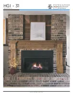
Place the HGI-31 system in an existing functional 

wood burning fireplace with a functional flue, this 

can be a manufactured fireplace or site built type. 

This location must have a natural gas supply line 

or LP gas supply.

When planning an appliance installation, it is 

necessary to determine the following information 

before installing:

• Where will the appliance be installed?    

See section 4

•  Gas supply piping.                                     

See section 5

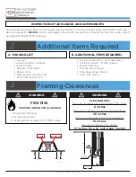
•  Framing and finishing details.                  

See section 4

Before beginning the installation, be sure that the 

following tools and supplies are at hand. 


•  Gloves


•  Safety Glasses


•  Phillips screwdriver


•  Non-corrosive leak-check solution


•  Wrenches

A. DESIGN AND INSTALLATION   

     CONSIDERATIONS

C. INSPECT THE APPLIANCE AND

     COMPONENTS

B. TOOLS AND SUPPLIES REQUIRED

The Outdoor Greatroom Co. 

disclaims any responsibility for, 

and the warranty will be voided by, 

the following actions: 

Asphyxiation Risk:

Sharp Edges:

WARNING

WARNING

WARNING

WARNING

WARNING

• Installation and use of any damaged 
components. 
• Modification of the assembly.
• Installation other than as instructed by the 
Outdoor Greatroom Company.

ANY SUCH ACTION MAY RESULT IN A FIRE HAZARD

Inspect appliance and components for damage. 
Damaged parts may impair safe operation.
• Do not install damaged, incomplete, or 
substitute components. Report damaged parts to 
your dealer.
• Carefully remove all components from 
packaging.
• Read all instructions before beginning 
installation. Follow these instructions carefully 
during installation to ensure maximum saftey and 
performance.

• This gas appliance is to be vented outdoors. 
• This unit must 

NOT

 be installed inside an 

   unvented appliance.

Wear protective gloves and safety glasses 
during installation.

Vented Decorative gas appliance: 

NOT

 a source 

of heat; 

NOT

 for use with solid fuel.

Do NOT use this appliance if any part of it has 

been underwater. Have an authorized service 

technician inspect the appliance and replace 

any part of the control system and any gas 

control which has been underwater.

Summary of Contents for HGI-31

Page 1: ...1 HGI 31 1 23 2018 www outdoorrooms com HGI 31 USER MANUAL...

Page 2: ...ely Immediately call your gas supplier from a neighbor s phone Follow the gas supplier s instructions If you cannot reach your gas supplier call the fire department Installation and service must be pe...

Page 3: ...les young children and other at risk individuals out of the room and away from hot surfaces Children and adults should be alerted to the hazards of high surface temperature and should stay away to avo...

Page 4: ...y As the owner of an Outdoor GreatRoom Company gas appliance you ll want to read and carefully follow all of the instructions contained in this owner s manual Pay special attention to all cautions and...

Page 5: ...and Information a Fuel b Gas Pressure c Gas Connection d LP Gas Setup e Natural Gas Setup 6 Installation a Venting the Appliance b Positioning Appliance c Testing the Appliance d Attaching the Surrou...

Page 6: ...Gas Fireplace CSA 2 22 2014 HGI 31 has been tested in accordance with US and Canadian requirements for vented gas fireplaces reference Natonal Fuel Gas Code ANSI Z223 1 NFPA54 or the Natural Gas and P...

Page 7: ...e warranty will be voided by the following actions Asphyxiation Risk Sharp Edges WARNING WARNING WARNING WARNING WARNING Installation and use of any damaged components Modification of the assembly Ins...

Page 8: ...tely Venting system 3 flex system Direct vent cap Phillips screw driver Flat head screw driver 5 16 Hex driver A PACKING LIST B ADDITIONAL ITEMS REQUIRED FIRE RISK PROVIDE ADEQUATE CLARANCE CLEARANCES...

Page 9: ...solution following testing Fittings and connections may have loosened during shipping and handling Before making gas connections ensure the appliance being installed is compatible with the available g...

Page 10: ...ons supplied with the Conversion Kit CONVERSION Kits MUST be installed by QUALIFIED INSTALLERS NATURAL GAS CONVERSION KIT PART NUMBER HGI 16 LIQUID PROPANE CONVERSION KIT PART NUMBER HGI 17 AN APPROVE...

Page 11: ...ing system at test pressures equal to or less than psi 3 kPa Provide a 1 8 in NPT plugged tapping accessible for test gage connection immediately upstream of the gas supply connection to the appliance...

Page 12: ...material and should be positioned so that appliance is not installed where carpet or other material will discolor or ignite from radiant heat See Page 7 for clearances After removal of obstructions in...

Page 13: ...ert Trim panels or surrounds shall not seal ventilation openings in the fireplace Ensure that chimney clean outs fit properly Smoke shelves shields and baffles may be removed if attached by mechanical...

Page 14: ...k for leaks you must remove the appliance from the wall cavity at this time and perform a check for leaks on all gas connections 3 Use the manual switch and remote control unit to ensure the appliance...

Page 15: ...n the fiber embers over the porting be sure not to interfere with the pilot assembly Pull the material apart so it is light and thin over the ports it is not necessary to use all of the material 5 Pos...

Page 16: ...secure the front 5 NOTE BOTH SPRING LOADED GLASS CLAMPS ARE NECESSARY FOR THE APPLIANCE TO FUNCTION PROPERLY AND SAFELY 6 Press heat deflector into position above glass door assembly Img 16 STEP SIX...

Page 17: ...ON LIGHTING AND OPERATION BEFORE LIGHTING BE SURE TO READ ALL WARNINGS AND SAFETY PRECAUTIONS If the screen becomes damaged the screen shall be replaced with the manufacturer s barrier for this applia...

Page 18: ...hest flame setting using the LARGE FLAME button Two beeps will indicate highest flame setting 2 Press and hold the LARGE FLAME button The control module will beep twice and the light on the remote wil...

Page 19: ...Operation A This appliance is lit electronically When lighting follow these instructions exactly B BEFORE LIGHTING perform a smell test for gas around the entire appliance Be sure to smell next to and...

Page 20: ...n Manual Operation 2 You will see or hear sparking occurring at the electrode 4 Standing pilot WARNING IN THE EVENT THE FLAME DOES NOT LIGHT 1 Flip switch to the OFF position 2 Wait 10 minutes 3 Smell...

Page 21: ...is programmed to turn off 10 minutes later Fan Not Responding Noise is caused by metal expanding and contracting as it heats up and cools down similar to the sound produced by a furnace or heating duc...

Page 22: ...AND SOLVING FLAME ISSUES Correct Flames should be blue at the base yellow orange on the top Not Enough Air The flames are tall or sooty on the ends open the air shutter Too Much Air The flames are al...

Page 23: ...e replaced prior to operating the appliance Burner Assembly Remove screen front and glass access panel examine logs for any damage replace or repair as needed Inspect for warping and corrosion Repair...

Page 24: ...Glass Door Assembly Burner Pan Blower Assembly Heat Shield 1 Termination Plate Fan Holder Heat Shield 2 Flue Gasket Power Cord Heat Deflector GF15A 05 02 00 GF15A 04 00 GF15A 00 04 HGI 03 HGI 01 GF15...

Page 25: ...ass Fitting 3 ST4 16 Screw Main Power Harness 41 NG Orifice Brass Fitting 1 SF1443 Valve Flex Line Backup Battery Pack LED Control Harness M12 3 Nut AP RQJ 015 00 GF15A 02 05 GV97 NAT HGI 06 AP RQJ 01...

Page 26: ...T SHOWN Log C Glowing Embers Log D Ember Log Log E Ember Media Natural Gas Conversion Kit Log F Remote Control Liquid Propane Conversion Kit Refractory Kit Left Right Back Side GF15A 00 55 GF15A 00 59...

Page 27: ...27 HGI 31 1 23 2018 www outdoorrooms com ITEM DESCRIPTION PART NUMBER Traditional Front Arched Front HGI ISTF HGI ISAF A B C Modern Front HGI ISMF A B C...

Page 28: ...28 www outdoorrooms com HGI 31 1 23 2018 B DIMENSIONAL INFORMATION C WIRING DIAGRAM See the section Vent Requ iremen ts for vent location...

Page 29: ...TEST POINT PRESSURE In the event of improper gas inlet pressure locate the valve by removing the decorative metal shield and looking into the unit Verify pressure with a manometer See pressure values...

Page 30: ...home construction warranty coverage initiates on the day occupation first occurs of the home or six 6 months following the sale of the HGI 31 Vented Gas Appliance by an authorized OGC dealer distribu...

Page 31: ...auses Use of fuels other than those specified in the operating instructions Installation or use of components not supplied with the appliance or any other components not expressly authorized or approv...

Reviews: