background image

OCT/SLO SERVICE MANUAL Version V.4

16

Initialization Process:

After  assembly  is  completed,  the  system  should  be  powered  up  and  ran  to  check
initialization.

Please follow the steps below :

1.


Power “ON” machine, check all cables are attached and boot up the computer
(Initialization program should run automatically after login). If Initialization fails
again, please contact the manufacturer.

2.


Initialization should take less than 10 minutes. If there are any problems during
initialization  it  may  be  helpful  to  enter  the  service  mode.  Otherwise  go  to  the
SLOOCT tab and click 

live

 to begin acquisition. (see User Manual)

Service mode:

1.


Go to the utilities tab.

2.


Click on “

Service”

 and enter the password ‘

room13

3.


Go to Diagnostics and you should see the ongoing communication between the
PC and the system during initialization.

4.


If the system fails to initialize check the power supply and cabling to the optical
head.

5.


Otherwise contact the manufacturer product service personnel.

Important Information:

C-Scan Settings

Transverse and Longitudinal Panes

: Sets image size and calibration parameters.

Stage INIT

:  Lists COM port number (if connected direct to PC should be port 1, if via

USB to serial converter should be port 3).

AutoAlignment:JIG:

 Trigger Voltage shows the lower limit for re-adjustment and upper

voltage the upper limit for re-adjustment.

Reconstruction

: used for image sizing and adjustment.

Summary of Contents for OCT

Page 1: ...ging System Service Manual Model B Version V 4 September 2005 Ophthalmic Technologies Inc 37 Kodiak Crescent Unit 16 Phone 1 416 631 9123 Toronto Ontario M3J 3E5 CANADA Fax 416 631 6932 www oti canada...

Page 2: ...itialization Process 16 Parts Replacement 17 21 Procedures and Warning 22 Service Protocol Scenners Replacement 23 Service Protocol MFN Stages Replacement 24 Service Protocol Mini LCD Replacement 25 S...

Page 3: ...with the reflected light from a reference mirror A photo detector unit detects and measure the interference and sends the signal to a computer that generates the OCT image Part of the light backscatt...

Page 4: ...thin the transverse area of the raster image due to the en face scanning used in the OCT SLO The user may select i the scanning depth range from 0 5 to 6 0 mm in user pre selected steps ii the scannin...

Page 5: ...ain patient records permitting a user friendly environment for clinical applications System components The OCT SLO system consists of The Scanner unit or Optical Head which contains the optical emitte...

Page 6: ...or mouse controlled combination of B Scan and C Scan Optional in Advance User mode Detailed Stack C Scan and Radial Scan and RNFL program Scan Pixels Adjustable 1024x1024 512x512 256x256 and128x128 S...

Page 7: ...z Pentium 4 1GB DDR RAM Monitor 19 Color LCD Monitor Control Input Devices Keyboard Mouse Joystick Storage 160GB Hard Disk ENVIRONMENTAL CONDITIONS Transport and Storage Temperature 10 to 60 deg C Rel...

Page 8: ...require cleaning are the forehead and the chin rest these are the parts that come with patient s contact regularly These parts should be cleaned between each examination with an alcohol prep swab The...

Page 9: ...tem power fuses by non authorized personal will void the system warranty and may cause major damage to some of the system key components Moving the OCT SLO system If the unit has to be moved to a new...

Page 10: ...Tray and the Computer shelf can be installed on either side of the motorized table Chinrest height adjustment Chinrest Joystick For Optical Head height position control Flexmount external fixation li...

Page 11: ...ir conditioning or at least a stable ambient temperature The system will be delivered in several parts the optical head and chinrest pre assembled the PC the up down table and the power supplies As we...

Page 12: ...pin Cables connected to boards Marked P 6110 and P6023 Serial Cable Parallel Cable Internal Monitor Cable Other Connections to the PC are External LCD Monitor VGA Cable Mouse Keyboard External Power C...

Page 13: ...Power connecting to Chin Rest power supply allows chin rest Up Down motion through the Joystick External Fixation wire connects to the Chin Rest Power Supply Optical Head Power Supply Note Please make...

Page 14: ...OCT SLO SERVICE MANUAL Version V 4 14 Connections bottom of the Optical Head Chin Rest P 20 connector Optical Head Power Supply connector...

Page 15: ...OCT SLO SERVICE MANUAL Version V 4 15 Image Capture and I O Boards PC NI Image Capture Board NI I O Board Connecting Cable I O Board to Capture Board...

Page 16: ...e User Manual Service mode 1 Go to the utilities tab 2 Click on Service and enter the password room13 3 Go to Diagnostics and you should see the ongoing communication between the PC and the system dur...

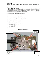
Page 17: ...her than OTI personnel The Replaceable parts in the system are X Y Galvoscanner Model 6210 X Y Scanners Controller Board Axis 3 4 MFN type Fiber Alignment stages Observation CCD Camera assembly Fixati...

Page 18: ...OCT SLO SERVICE MANUAL Version V 4 18 Observation CCD Camera assembly X Y Scanners Controller Board X Y Scanners...

Page 19: ...OCT SLO SERVICE MANUAL Version V 4 19 Fixation Mini LCD Assembly Optical Head Interface Board Safety Board SLO Detector...

Page 20: ...OCT SLO SERVICE MANUAL Version V 4 20 MCB Stages Controller Board X Y Scanners Controller Board SLD Pilot 4 Controller OCT Detector Electronics SLO Detector Main Ref Stage...

Page 21: ...e blue fiber may cause degradation of final image quality or complete machine failure Pinching of the electrical cables may cause hindrance of movement of the optical head or in ability to close the c...

Page 22: ...at the driver board and scanner head 3 Ensure system is powered up and the software is running correctly 4 Go to service menu 5 Click on c scan settings tab switch between this tab and the SLOOCT capt...

Page 23: ...t the axis 4 MFN is removable 11 Slide out the axis 4 MFN 12 Feed through the cable for the new MFN and position being careful not to apply too much pressure on the 3x URM3 5 mounting assembly for fib...

Page 24: ...at the scan pattern is clearly displayed on the monitor in a sharp fashion To do this you may need to adjust the power of the SLD drive current as set on the pilot 2 or 4 to zero If this is the case d...

Page 25: ...Attach Camera alignment JIG to lens barrel 2 Move external chinrest illuminator to backlight the opaque target on the JIG assembly 3 Check camera image is beingdisplayed correctly on the PC monitor c...

Page 26: ...off power to PILOT 3 Remove D type connector and unplug safety cables these go to scanner feedback positions 4 Unscrew power cable from terminal 14 and 16 5 Replace new PILOT attach power cables but...

Page 27: ...cked Replacement of scanners Replacement of PILOT controller Preferably two people are required one to use the IR viewer hold the power meter head and one to call out measurements For this measurement...

Page 28: ...appen when the voltage is switched from 120V to 100V on the isolation transformer An earlier optical cause reported should now be solved Another possible solution is to replace the X scanner cable bet...

Page 29: ...parts which are not listed in this service manual or the entire optical head is against OTI recommendation and it will void any warranty provided by the manufacturer OTI OTI will be only responsible...

Page 30: ...OCT SLO SERVICE MANUAL Version V 4 30 JIGS for Setup and Alignment Jig for LCD Alignment Jig for Image Calibration Jig for Camera Alignment...

Page 31: ...OCT SLO SERVICE MANUAL Version V 4 31 OCT SLO Wiring Diagrams S1051A0 Electrical Schematic...

Page 32: ...OCT SLO SERVICE MANUAL Version V 4 32 S1051A0 Interface Board Drawing...

Page 33: ...OCT SLO SERVICE MANUAL Version V 4 33 S1051A0 Optical Head Power Supply Drawing...

Reviews: