background image

14

Installation

4.2 

Mounting process 

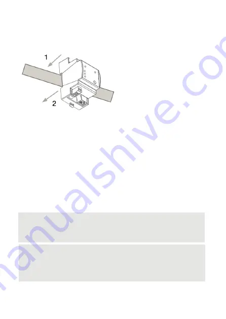
The e:cue SYMPL Node is designed to mount onto a 35 mm DIN rail 
(EN 60715) in a vertical position. 

1.  Clip the device to the rail from 
top. 

2.  Gentle pressure is then 
applied to the top front to snap it 
in place. The SYMPL input Node 
has been mounted successfully.

You can also mount the e:cue 

SYMPL Node on any flat vertical surface. Use a 3 to 3.5 mm screw for the 

hanger hole.

For mechanical stability, mounting on a rail is recommended.

4.3 

Ethernet connection

The pin-assignment of the Ethernet port corresponds to RJ45 standards. 
You can use every common Ethernet component, like cable, splitters, and 

switches. Connect the SYMPL input Node at the designated Ethernet 
interface with a patch cable (RJ45, CAT5).

i

Never connect more than one SYMPL Node in factory state 

to a network. The identical IP addresses will conflict and 

disturb proper communication.

i

The Ethernet port of the SYMPL Node is not designed for 

inter-building connections with power and lighting transients. 
Use only intra-building networks to connect the SYMPL 

Nodes and Cores.

Summary of Contents for AB444200035

Page 1: ...AB444200035 e cue SYMPL input Node Setup Manual Installationsanleitung Our Brand www osram com ecue Light is OSRAM...

Page 2: ...or damages All dimensions should be verified using an actual part Except for internal use relinquishment of the instructions to a third party duplication in any type or form also extracts as well as e...

Page 3: ...Reset 10 3 General remarks 11 3 1 Transport 11 3 2 Unpacking 11 3 3 Warranty regulations 12 3 4 Maintenance and Repair 12 3 5 Disposal 12 3 6 Support 13 4 Installation 13 4 1 Installation conditions 1...

Page 4: ...weise 27 12 1 Transport 27 12 2 Entpacken 28 12 3 Garantiebestimmungen 28 12 4 Reparatur und Wartung 28 12 5 Entsorgung 28 12 6 Technischer Support 29 13 Installation 29 13 1 Installationsbedingungen...

Page 5: ...05 Table of Contents Inhalt 18 Zertifizierung 37 Dimensions Abmessungen 38 Application examples Anwendungsbeispiele 39...

Page 6: ...06 English...

Page 7: ...xclamation mark warns about possible damage of the device itself or connected devices i The information symbol gives general hints and informs about handling and procedures for use of the device 1 2 G...

Page 8: ...upport 20 mA constant current input configurable with four slide switches The e cue SYMPL input Node can be powered by an external power supply or via Power over Ethernet It is easily mounted on stand...

Page 9: ...thernet LAN activity 7 Status LED Device status 8 Identify button 9 Power supply Vcc Vcc left to right 10 e net Ethernet 2 3 User interface LEDs The SYMPL input Node has 11 LEDs The 11 LEDs show the b...

Page 10: ...Input status 1 to 8 Off Input value is smaller than the Digital Threshold Low On Input value is bigger than the Digital Threshold High Change the Digital Thresholds in the properties of the Node in th...

Page 11: ...hanges apply 3 General remarks 3 1 Transport Only transport the device in its original packaging This protects the device from damage 3 2 Unpacking Only unpack the e cue SYMPL input Node at its instal...

Page 12: ...ls and of the device is the responsibility of the respective user and for his account in all other matters the retrieval obligation for packing materials and the device is subject to the statutory reg...

Page 13: ...o e net and to power supply The sequence of cabling is not defined Supply the SYMPL input Node with power after all cabling is completed it starts booting 4 1 Installation conditions Installation posi...

Page 14: ...unting on a rail is recommended 4 3 Ethernet connection The pin assignment of the Ethernet port corresponds to RJ45 standards You can use every common Ethernet component like cable splitters and switc...

Page 15: ...running of the SYMPL Node To connect the device to a power supply unit use the provided 2 pole terminal and lay the wires as stated on the front label The voltage assignment is left V and right V Tur...

Page 16: ...network configuration You can either adjust the network settings with SYMPHOLIGHT or using the web interface of the SYMPL input Node 5 1 Default network properties The SYMPL input Node has as factory...

Page 17: ...submit the changes The network configuration of the SYMPL input Node is completed 5 3 Network configuration with the web interface 1 Open a common web browser on a connected PC Enter the SYMPL input...

Page 18: ...ick Submit to apply the settings The network configuration of the SYMPL input Node is completed i The employment of a discrete network is recommended i Note down all employed and if applicable reserve...

Page 19: ...te firmware in the context menu of the SYMPL input Node or click the Update button in the head toolbar 7 Dismounting Disconnect all attached cables Dismount the e cue SYMPL input Node from the rail by...

Page 20: ...er over Ethernet PoE IEEE 802 3af Power consumption max 1 2 W Operating temperature 0 50 C 32 122 F Storage temperature 10 70 C 14 158 F Operating storage humidity 0 80 non condensing Protection class...

Page 21: ...20 mA inputs user configurable Available on pins 5 8 set by slide switch input impedance shunt 150 Maximum input voltage 12 V DC Maximum input current 30 mA 1 x common ground connector 9 Certificatio...

Page 22: ...22 Deutsch...

Page 23: ...Das Ausrufezeichen warnt vor Sch den am Produkt oder an angeschlossenen Ger ten i Das Informationssymbol gibt generelle Hinweise und informiert ber Handhabung oder Verfahren zur Verwendung des Ger tes...

Page 24: ...V Eing nge vier davon k nnen auf 20 mA Konstantstrom umgeschaltet werden Mit Spannung versorgt wird der SYMPL input Node von einem externen Netzteil oder ber Power over Ethernet PoE Die Montage erfolg...

Page 25: ...2b Eing nge 0 10 V oder 0 4 20 mA 5 8 links nach rechts 3 Schiebeschalter Betriebsart Eing nge 5 8 links 0 10 V rechts 0 4 20 mA 4 LED Eingangsstatus 1 8 links nach rechts 5 LED Fehler Error 6 LED e...

Page 26: ...Aus es liegt keine Fehlermeldung vor An Falls konstant rot ist ein Fehler aufgetreten Dies kann ein interner Fehler oder eine Fehlfunktion sein oder ein externer Fehler wie Kurzschluss der Datenanschl...

Page 27: ...D leuchten Lassen Sie den Taster wieder los Der Node bleibt nun im Bootloader Modus und ist bereit f r ein Herunterladen einer Firmware Um den Bootloader Modus zu beenden dr cken Sie den Identify Tast...

Page 28: ...Gew hrleistung zeitlich unterschiedlich befristet sein Die Garantie und Gew hrleistungsbestimmungen finden sich in der Regel im Angebot und in der Auftragsbest tigung Zus tzlich sind Informationen da...

Page 29: ...m 13 Installation Zur Installation vom e cue SYMPL input Node montieren Sie diesen auf einer Hutschiene und schlie en die Spannungsversorgung eine e net Verbindung und Lasten an Die Reihenfolge der Ka...

Page 30: ...ngen Sie das Ger t oben in die Hutschiene ein 2 Dr cken Sie leicht auf das Geh use so dass die untere Verriegelung auf der Hutschiene einrastet Das Ger t ist nun montiert Der e cue SYMPL Node kann auc...

Page 31: ...ample Anwendungsbeispiel auf Seite 39 f r Beispiele 13 5 Stromversorgung Verbinden Sei den e cue SYMPL input Node mit einem NEC Class 2 24 V DC Netzteil Das Anliegen von Stromversorgung am Node entspr...

Page 32: ...nutzerhandbuch ist auf www ecue com verf gbar Die Netzwerkeinstellungen des SYMPL input Nodes sind voreingestellt Um nderungen an den Netzwerkeinstellungen vornehmen zu k nnen ist die erfolgreiche Ins...

Page 33: ...HOLIGHT das Kontextmen von dem SYMPL input Node mit einem Rechtsklick auf das Ger t 2 W hlen Sie Configure Network aus 3 Legen Sie die IP Adresse die Subnet Maske und die DHCP Einstellungen nach Ihren...

Page 34: ...ie Einstellungs Seite wird angezeigt 3 Legen Sie die Netzwerkeinstellungen unter der Rubrik Device Basics nach Ihren Anforderungen fest Sie k nnen hier ebenfalls das Zugangspasswort zu den Webschnitts...

Page 35: ...PL input Node abzubauen trennen Sie alle verbundenen Kabel und Anschl sse von dem Ger t Entfernen Sie den SYMPL input Node von der Hutschiene indem Sie die schwarze Hutschienen Entriegelung ziehen und...

Page 36: ...tungsaufnahme max 1 2 W Betriebstemperatur 0 50 C Lagertemperatur 10 70 C Betriebs Lagerfeuchte 0 80 nicht kondensierend Schutzklasse IP20 Elektrische Sicherheit SELV Geh use Selbstl schendes PC ABS n...

Page 37: ...V auf Pins 1 8 Eingangsimpedanz 40 k 4 x 0 10 V oder 0 4 20 mA konfigurierbar auf Pins 5 8 mit Schiebeschalter Eingangsimpedanz Ableitwiderstand 150 Maximale Eingangsspannung 12 V Maximaler Eingangss...

Page 38: ...38 Dimensions Abmessungen All dimensions in mm Alle Abmessungen in mm 62 53 5 90 5...

Page 39: ...39 Application examples...

Page 40: ...mode switch for input 7 and 8 to 0 4 20 mA Betriebsart f r Eingang 7 und 8 mittels Schiebeschalter auf 0 4 20 mA setzen 12 V DC 12 V DC Sensor 4 20 mA Sensor 4 20 mA When connecting multiple 2 wire s...

Page 41: ...0 4 20 mA Betriebsart f r Eingang 8 mittels Schiebeschalter auf 0 4 20 mA setzen Iout 12 V DC Sensor 4 20 mA With 3 wire sensors all sensors can have the same power supply Bei 3 Draht Sensoren k nnen...

Page 42: ...s Betriebsart f r verwendete Eing nge mittels Schiebeschalter auf 0 10 V setzen Alle acht Eing nge sind f r bis zu 12 V ausgelegt 12 V DC The mode switches have to be set to voltage input Otherwise th...

Page 43: ...gies com OSRAM GmbH Sales Operations Karl Schurz Str 38 33100 Paderborn Germany 49 5251 54648 0 support ecue com www ecue com Head office Zentrale Marcel Breuer Strasse 6 80807 Munich Germany Phone 49...

Reviews: