10
3.10.1 Fitting instructions
3.9.6 Discharge pipe
!
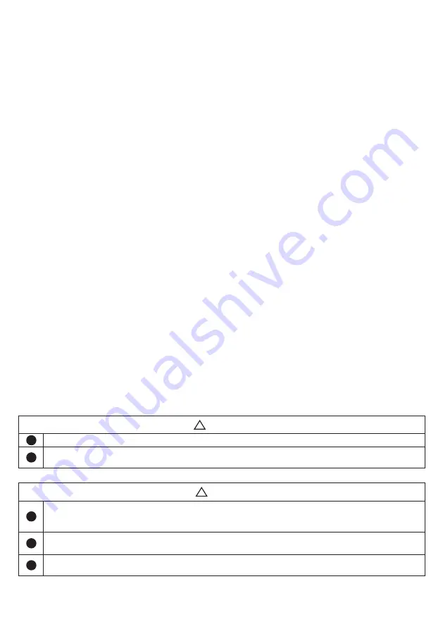
CAUTION
!
The product should be placed in a room with a drain, in accordance with the wetroom
standard / latest TEK. Alternatively, fit an automatic stop valve with sensor and overflow
from safety valve to drain.
!
The product should be properly aligned vertically and horizontally, on a floor or wall suitable for
the total weight of the product when in operation. See type plate.
!
The product must have a clearance for servicing of 40 cm in front of the cover / 10 cm over the
top connection.
!
WARNING
!
The product should be filled with water before the power is switched on.
!
Any overflow pipe from safety valves must be of a suitable size, clear, undamaged and frost-
free with a fall to the drain.
Connect the tundish outlet to the discharge pipe.
Install the Tundish in a vertical position within
a maximum of 600 mm from the Temperature
and Pressure Relief Valve drain connection and
away from electrical components. Ensure the
expansion relief pipework discharges through
the tundish. Tundish pipework must be 22 mm
with a minimum vertical length of 300 mm below
tundish. Maximum permitted length of 22 mm
pipework is 9 m. Each bend or elbow is equiva-
lent to 0.8 m of pipework. All pipework must
have continuous fall and discharge in a safe, vis-
ible position. If any doubt, refer to Building Regu-
lation G3. Discharge pipe must be dedicated to
the cylinder and must not be used for any other
purpose.
3.10 Flow and Returns and Motorized valve
The boiler primary flow and return connections
should be made connections 3 & 4. The motor-
ized valve can be connected to either the primary
flow or return pipe. The primary flow and return fit
-
tings are 3/4’’ BSP female. The valve has 22mm x
copper connections. The direction of primary flow
in the upper coil is bottom to top. The maximum
operating temperature of the primary flow would
typically be 82°C.
For electrical connection of the motorized valve
and immersion heater, please read Electrical
Installation Instructions. (Page
??
).
The Solar flow and return connections should be
made to the lower connections 1 & 2. Tempera-
ture control from the Solar circuit is achieved us-
ing a differential solar controller. This controller
must be wired in series through the thermal cut-
out on the OSO thermostat. If Solar Collectors
are to be installed at a later date then connect the
boiler primaries to the lower coil. If boiler prima-
ries are connected to lower coil then the thermo-
stat must be removed , and the grey wire uncoiled
from inside thermostat. The thermostat must then
be replaced inserting both wires into sensor pock-
et, resetting temperature to 60°C. The direction of
solar primary flow in the solar coil is top to bottom.
The solar circuit must be installed with a solar hy-
draulic station which must incorporate a pump and
non-return valves in both flow and return within
the solar circuit. This system will prevent thermal
siphoning when the pump is not active
.
Temperature sensors for the cylinder provided
with the differential controller should be inserted
into the pockets provided.
There is no maximum primary temperature from the
solar system and primary temperatures in excess
of 100°C are not unusual. All components on the
solar circuit must be suitable for these higher
temperatures. Should the solar circuit be installed
incorrectly, then all approvals and guarantees of the
cylinder are invalid.
Summary of Contents for Delta Twincoil DTC 200
Page 26: ...26 NOTES ...


