Osaka COC 30 Operating Instructions Manual Download Page 8

OSAKA OPERATING INSTRUCTIONS –COC 30- Page 

8


These commands have a bistable function, which means that 
at the  first command the AUX output is activated whereas on 
the second it is deactivated. 
In this mode, the AUX output can also be switched off 
automatically  after a certain time that can be set under the “ 

AO

t” parameter. 

With "AOt" = 0 the output is only activated and deactivated 
manually, using the DOWN/AUX key or the digital input. 
= 5 – mutable alarm: the AUX output is activated together with 
the buzzer when alarm conditions exist and, like the buzzer, it 
can be muted by pressing any key. 
= 6  – non-mutable alarm: the AUX output is activated when 
alarm  conditions exist and remains activated for as long as 
such conditions persist. 
 

4.8 – DIGITAL INPUTS 

The instrument has three settable digital inputs for free voltage 
contacts. 
All the digital input setting parameters are contained in the 

“ 

In”

group. 

The function logic of the digital inputs is established by the 
parameters 

“i1L”, “i2L”, “i3L” 

, which can be programmed as 

follows: 
= On – contact normally open: the programmed function occurs 
on the closure of the contact connected to the input. 
= OFF  – contact normally closed: the programmed function 
occurs  on the opening of the contact connected to the digital 
input. 
The action of the digital inputs can be delayed using the 
following parameters: 

“i1d”, “i2d”, “i3d” 

, which can be programmed in seconds. 

With regards to operation, the digital input acts according to 
the 

"i1F", “i2F”, and “i3F” 

parameters, which can be 

programmed as: 
= 0 – not operative 
= 1  – external alarm signal: on input intervention, the alarm is 
activated and the upper display alternately shows 

"ALn" 

(where n is the number of the digital input) and the temperature 
measured. 
= 2  – Remote control of auxiliary output AUX: the digital input 
is used to command the auxiliary output AUX as described in 
operation mode "AOF" = 4 of the auxiliary output 
= 3 – Steam injection remote control: the digital input operates 
as the instrument’s INJ key. 
= 4 – Steam injection block: the intervention of the digital input 
causes steam injection blockage. The function can be useful if 
the  instrument does not have the steamer probe and one 
wishes to block injection by means of a steamer thermostat. 
= 5 – Pulse command for switching on the extractor output for 
multiple command. This can be used to facilitate the command 
of the single extractor when more than one appliance is fitted 
to an oven. If one desires to command a single extractor from 
a number  of instruments, it is possible to do so by 
programming the former  with “ECn”=OFF and all the others 
with “ECn” =On, connecting the  EXTR relay output of the 
former in such a way that it commands the  extractor, 
connecting the EXTR relay outputs of all the others in parallel 
and therefore at the digital input of the former, which will have 
suitably programmed the digital input with this operation mode. 
 

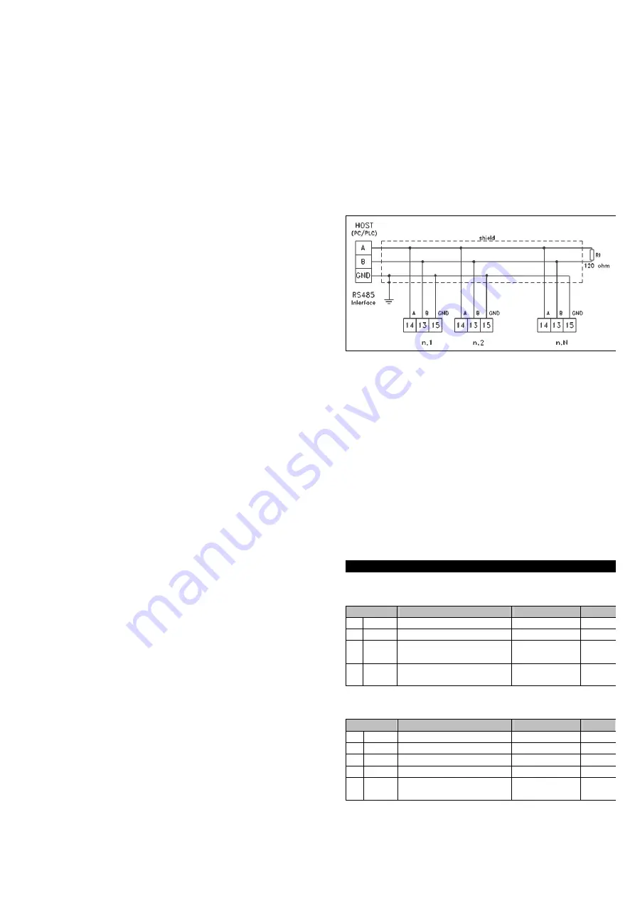
4.9 - RS 485 SERIAL INTERFACE 

The instrument can be equipped with a RS 485 serial 
communication interface, by means of which it is possible to 
connect the regulator with a net to which other instruments 
(regulators of PLC) are connected, all depending typically on a 
personal computer used as plant supervisor. Using a personal 
computer it is possible to acquire all the function information 
and to  program all the  instrument’s configuration parameters. 
The software  protocol adopted for  COC is a MODBUS RTU 
type, widely used in  several PLC and supervision programs 

available on the market  (COC series protocol manual is 
available on request). 
The interface circuit allows the connection of up to 32 
instruments on the same line. 
To maintain the line in rest conditions a 120 Ohm resistance 
(Rt) must be connected to the end of the line. 
The instrument is equipped with two terminals called A and B 
which have to be connected with all the namesake terminals of 
the net. 
For the wiring operation they must be interlaced with a double 
cable  (telephonic type) and all the GND terminals must be 
connected to the ground.  
Nevertheless, particularly when the net results very long  or 
noised and being present potential differences between the 
GND terminals, it is advisable to adopt a screened cable wired 
as in the drawing. 

 
if the instrument is equipped with a serial interface, the 
parameters to be programmed are the following, all present in 
the parameters group 

“ 

SE” 

:  

"Add" 

: Address of the station. Set a different number for each 

station, from 1 to 255. 

"bau" 

: Transmission speed (baud-rate), programmable from 

2400  to 38400 baud. 1 =2400 baud, 2 =4800 baud, 3 =9600 
baud, 4= 19200 baud , 5 =38400 baud. All the stations have to 
have the same transmission speed. 

"PAC" 

: Programming access. If programmed as "LoC" this 

means  that the instrument is only programmable from the 
keyboard, if programmed as "Lor" it is programmable both from 
the keyboards and serial line. 
If an attempt is made to enter the programming from the 
keyboard  whilst a communication through the serial port is in 
progress the  instrument will visualise 

"bSy" 

to indicate the 

busy state. 
 

5 –  PROGRAMMABLE PARÁMETER S


5.1 - PARAMETERS TABLE 
“ 

SP” Group 

(Set Point parameters) 

Par.


Description


Range


Def.


SP1

  TOP Set Point 

SPL ÷ SPH 

SP2

  FLOOR Set Point 

SPL ÷ SPH 

SPL 

(com) 

Minimum Set Point 

-99 ÷ SPH 

SPH 

(com) 

Maximum Set Point 

SPL ÷ 999 

999 


 “ 

rG” Group 

(temperature regulation and power control 

parameters) 

Par.


Description


Range


Def.


OP1

  TOP power 

0 ÷ 100 % 

50 

OP2

  FLOOR power 

0 ÷ 100 % 

50 

tCP

  Power control Cycle time 

1 ÷ 999 seg. 

30 

PSP

  Power setting mode 

1 - 2 – 3 

HS1

  Regulator differential 1 

(TOP) 

1 ÷ 999 

Summary of Contents for COC 30

Page 1: ...UNCTIONAL DATA 7 5 MEASUREMENT RANGE TABLE 7 6 INSTRUMENT ORDERING CODE DE 1 INSTRUMENT DESCRIPTION 1 1 GENERAL DESCRIPTION Model COC 30 is a microprocessor based digital controller designed to command ovens particularly those used in bakeries The instrument s main feature is the possibility to have separate control over the temperature and heating powers for the TOP and FLOOR of the oven as well ...

Page 2: ...functions The panel therefore shows all the displays and all the leds to be active with the exception of the Stand by Led off OFF STAND BY meaning that the control device does not activate any control function with the exception of the light command The display is therefore off with the exception of the Stand by led which is lit If the automatic switch on timer is present in the OFF status it is p...

Page 3: ...ng of the CLOCK led and the flashing of the hh mm separation led At the programmed time the control device will switch on automatically To deactivate the switching on timer press the START key for 1 second or switch the instrument on ahead of time If you wish the oven to switch on and switch off automatically in this mode the cooking time must also be programmed once the cEF parameter has been pro...

Page 4: ...s possible to the instrument and located in a position that can easily be reached by the user and marked as instrument disconnecting device which interrupts the power supply to the equipment It is also recommended that all the electrical circuits connected to the instrument must be protect properly using devices ex fuses proportionate to the circulating currents It is strongly recommended that cab...

Page 5: ...taneously on therefore if the two resistances are equal the maximum power absorbed is 50 This occurs in any case when without the limiter being on the sum of the two powers is less than 100 Therefore the function with the power limiter on starting from the count of the cycle time is as follows 1 the TOP output remains on for the time tCP 2 x OP1 100 2 Both outputs remain off for the time tCP 2 tCP...

Page 6: ...ill activate when the temperature value rises above the AnH alarm threshold and will deactivate when it drops below the AnH HAn value 4 4 OVEN LIGHT CONTROL The LIGHT key can be used to activate deactivate the LIGHT output the activation of the output is therefore indicated by the LIGHT led When the controller is switched off the output is in any case switched off but in standby mode the output ca...

Page 7: ...eam injected being extracted On In this case the output if on switches off when steam injection starts and remains switched off for the entire duration of injection and even after it finishes for a certain time in sec that can be set under the Edt parameter Moreover using the EAS On parameter it is possible for the extractor output to be activated if it is not already automatically when cooking is...

Page 8: ...ands the extractor connecting the EXTR relay outputs of all the others in parallel and therefore at the digital input of the former which will have suitably programmed the digital input with this operation mode 4 9 RS 485 SERIAL INTERFACE The instrument can be equipped with a RS 485 serial communication interface by means of which it is possible to connect the regulator with a net to which other i...

Page 9: ...larm 1 0 999 seg 0 38 A2t com Alarm type AL2 Ab dE Ab 39 A2L com Lower threshold alarm 2 99 999 99 40 A2H com Upper threshold alarm 2 99 999 999 41 HA2 com Hysteresis alarm 2 1 999 1 42 A2d com Delay activation of alarm 2 0 999 sec 0 43 Pod com Disabling alarms on switching on 0 999 min 0 St Group steam control parameters Par Description Range Def 44 SPS Steamer regulator Set Point 99 999 130 45 H...

Page 10: ... External alarm signal on input intervention the alarm is activated and the upper display alternately shows AL1 and the temperature measured 2 Auxiliary output AUX remote control the digital input is used for the command of the auxiliary output AUX as described in the AOF 4 operating mode of the auxiliary output 3 steam injection remote control the digital input operates as the instrument s INJ ke...

Page 11: ...R output function in relation to the relative key as bistable OFF or monostable ON In practice bistable operation means that the first time the EXTR Key is pressed the output activates and remains activated whereas the second time deactivates it Monostable operation means that the output is activated only when the key is pressed AO Group AUXILIARY OUTPUT PARAMETERS for setting the AUX output AOF A...

Page 12: ...with a detailed description of the faults found without any fees or charge for OSAKA except in the event of alternative agreements 7 TECHNICAL DATA 7 TECHNICAL DATA 7 1 ELECTRICAL DATA Power supply 24 115 230 VAC 10 Frequency AC 50 60 Hz Power consumption 9 VA approx Input s up to 4 inputs for temperature probes tc J K or RTD Pt 100 IEC 2 wires 3 digital inputs for free voltage contacts Output s U...

Page 13: ...UT RANGE tc J Model C SEn J 50 999 C 58 999 F tc K Model C SEn CrA 50 999 C 58 999 F Pt100 IEC Model D 50 600 C 58 999 F 7 6 INSTRUMENT ORDERING CODE COC 30 a b c d e f g hh a INPUTS TYPE C thermocouples J K D thermoresistances Pt100 b SUPPLY D 230 VAC C 115 VAC A 24 VAC c AUXILIARY PROBE INPUT none A YES d AUXILIARY OUTPUT none R YES e STEAMER PROBE INPUT none V YES f COMMUNICATION INTERFACE No i...

Reviews: