edition 2019/04
© 2019/04
OSA Opto Light GmbH · Phone +49-(0)30-65762683 · [email protected]
Betrieb (
Betrieb (
Betrieb (
Betrieb (Rechner S
Rechner S
Rechner S
Rechner Steuerung)
teuerung)
teuerung)
teuerung)
Im Lieferumfang befindet sich eine Windows-
Software zur Steuerung des LED-Moduls.
Die gelbe LED-Anzeige (PC-Control) leuchtet,
wenn der PC durch ein USB Kabel mit der
Steuerung OEM-062 SY verbunden wurde
Als nächste Schritt wählt man die entsprechende
COM-Schnittstelle aus und stellt die Verbindung
durch Druck auf den Button „Connect“ her
Mit dem Schieberegler kann der LED-Strom im
Bereich von 10%-100% eingestellt werden
Der
Power-Button
schaltet
das
Modul
softwareseitig nur dann ein, wenn kein Fehler
vorliegt und der Power ON/OFF-Schalter am
Steuereinheit auf ON geschaltet wurde.
Durch drucken dem Button „Save Power-Value
to Module“ wird der Wert des Schiebereglers im
Steuereinheit gespeichert.
Dieser Wert wird bei Start des Moduls ohne PC
automatisch aufgerufen.
Die Moduladresse ist standardmäßig 01 und
muss nur geändert werden, wenn mehrere
Module mit der Software betrieben werden
sollen.
Im
Statusfenster
wird
der
Zustand
der
Datenverbindung, der Kabelverbindung, der
Temperaturüberwachung sowie des ON/OFF-
Zustands angezeigt.Dabei gilt: Grün = ON/OK
Rot = OFF/Fehler
Außerbetriebnahme
Außerbetriebnahme
Außerbetriebnahme
Außerbetriebnahme
Bitte trennen Sie das Netz vom Netzteil um unnötigen
Stromverbrauch zu vermeiden
Operation (
Operation (
Operation (
Operation (PC
PC
PC
PC control)
control)
control)
control)
The delivery includes a Windows software for
controlling the LED module
The yellow LED indicator (PC Control) turns on
when the PC is connected with a USB cable
to
the OEM-062 SY controller
The next step is to select the corresponding
COM interface and establish a connection by
pressing the "Connect" button
The slider bar can be used to set the LED current
in the range of 10% -100%
The power button in the program only switches
on the module if there is no error and the power
ON / OFF switch on Controller unit has been
switched to ON
Pressing the button "Save Power-Value to
Module" stores the value of the slider bar in the
Controller unit.
This value is called automatically when the
module is started without a PC.
By default, the module address is 01 and only
needs to be changed if several modules are to be
operated with the software.
The status window shows the status of the data
connection, the cable connection, the
temperature monitoring and the ON / OFF
status. Here: Green = ON / OK Red = OFF /
Error
Shutting
Shutting
Shutting
Shutting down
down
down
down
Please disconnect the power supply to avoid un-necessary
power consumption
Warn- und Sicherheitshinweise
Warnings and safety instructions
Diese Power LEDs emittieren im Betrieb intensive, in
Abhängigkeit vom Typ auch unsichtbare optische
Strahlung (UV oder IR), die auch bei kurzzeitiger
Expositon für die Augen schädlich sein können.
These Power LEDs emit during operation intense
optical radiation, depending on the type also
invisible (UV or IR), which may be harmful to eyes,
even for brief periods.
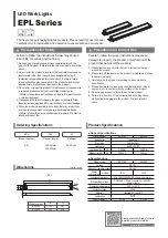
Benutzeroberfläche der Steuerungssoftware / User interface of the LED control software