12
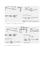
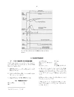
Fig. 4.4. Pole-Zero Adjustment Using a Square Wave Input to the Preamplifier.
the switch can be set at Threshold and the manual
control just below the switch can then be used to
select the level manually as follows:
a.
Remove all radioactive sources from the vicinity
of the detector. Set up the system as for normal
operation, including detector bias.
b.
Set the BLR switch at Threshold and turn the
control fully clockwise, for 300 mV.
c.
Observe the unipolar output on the 100mV/cm
scale of the oscilloscope, using 5 µs/cm horizontal
deflection. Trigger the oscilloscope with the Busy
output from the 572A.
d.
Reduce the control setting until the baseline
discriminator begins to trigger on noise; this
corresponds to about 200 counts/s from the Busy
output. Adjust the trigger level according to the
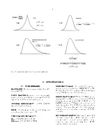
information in Fig. 4.5.
If a ratemeter orcounter-timeris available, it can be
connected to the Busy output and the threshold
level can then be adjusted for about 200 counts/s.
4.8. OPERATION WITH SEMICONDUCTOR
DETECTORS
CALIBRATION OF TEST PULSER
An ORTEC
419 Precision Pulse Generator, or equivalent, is
easily calibrated so that the maximum pulse height
dial reading (1000 divisions) is equivalent to a
10-MeV loss in a silicon radiation detector. The
procedure is as follows:
Summary of Contents for 572A
Page 6: ...vi...


