5
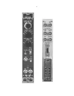
2.2. CONTROLS
GAIN
Ten-turn precision potentiometer for
continuously variable direct-reading gain factor of
X0.5 to X1.5.
COARSEGAIN
Six-positionselectorswitchselects
feedback resistors for gain factors of 20, 50, 100,
200, 500, and 1 K.
INPUT ATTENUATOR
Jumper on printed circuit
board selects an input attenuation factor of 1 or 10
(gain factor of X1 or X0.1).
POS/NEG
Toggle switch selects input circuit for
either polarity of input pulses from the preamplifier.
SHAPING TIME
Six-position switch selects time
constant for active filter network pulse shaping;
selections are 0.5, 1, 2, 3, 6, and 10 µs.
PZ ADJ
Potentiometer to adjust pole-zero
cancellation for decay times from 40 µs to
4444
.
Factory preset at 50 µs to match normal
characteristics of ORTEC preamplifiers.
BLR
Toggle switch selects a source for the gated
baseline restorer discriminator threshold level from
one of three positions.
!
!!
!
Auto
The BLR threshold is automatically set to
an optimum level as a function of the signal
noise level by an internal circuit. This allows
easy setup and very good performance under
most conditions.
!
!!
!
PZ Adj
The BLR threshold is determined by the
threshold potentiometer. The BLR time constant
is greatly increased to facilitate PZ adjustment.
This position may give the lowest noise for
conditions of low count rate and/or longer
shaping times.
!
!!
!
Threshold
The BLR threshold is set manually
by the threshold potentiometer. Range is 0 to
300 mV referred to the positive output signal.
The BLR time constant is the same as for the
Auto switch setting.
DC
Screwdriverpotentiometer adjuststheunipolar
output baseline dc level; range, +100 mV to
-100 mV.
2.3. INPUT
INPUT
Type BNC front and rear panel connectors
accept either positive or negative pulses with rise
times in the range from 10 to 650 ns and decay
times from 40 to 2000 µs; Z
in
-
500Ω, dc coupled;
linear maximum, 1 V (10V with attenuator jumper
set at X0.1); absolute maximum, 20 V.
2.4. OUTPUTS
UNI
Unipolar front panel BNC with Z
in
, <1Ω and
rear panel BNC with Z
in
= 93Ω. Short-circuit proof;
prompt; full-scale linear range 0 to +10 V; active
filter shaped and dc restored; dc level adjustable to
±100 mV.
Bi
Bipolar front panel BNC with Z
in
<10Ω and rear
panel BNC with Z
in
= 93Ω. Short-circuit proof;
prompt output with positive lobe leading and linear
range of ±10V; active filter shaped.
BUSY
Rear panel BNC with Z
in
<10Ω provides a
+5 V logic pulse for the duration that the input pulse
exceeds the baseline restorer discriminator level.
Connect to the ORTEC MCA Busy input for dead
time correction.
INH
Inhibit rear panel BNC with Z
in
<10Ω provides
a n5 V logic signal when an internal pulse
pileup occurs: width
-
6τ in coincidence with the
pileup;tobeusedforanMCAanticoincidenceinput
to prevent storage of pileup data in the spectrum.
CRM
Count Ratemeter rear panel BNC furnishes
a n5 V logic signal for every linear input
pulse; width, 300 ns; to be used as an input to a
ratemeter or counter.
PREAMP POWER
Rear panel standard ORTEC
power connector; Amphenol 17-10090; mates with
captive and non-captive power cords on all
standard ORTEC preamplifiers.
2.5. ELECTRICAL AND MECHANICAL
POWER REQUIRED (not including any load on
the Preamp Power connector)
+24 V, 100 mA; -24 V, 105 mA;
+12 V, 85 mA; -12 V, 50 mA.
FRONT PANEL DIMENSIONS
NIM-standard
single-width module (1.35 by 8.714 in.) per TID-
20893.
Summary of Contents for 572A
Page 6: ...vi...


