IG-175-EN version 02; 17/06/2016
28
Installation and connections
General Instructions
ekor.gid
6.2. ekor.gid connections
6.2.1. Wall-mounted
Once the ekor.gid unit has been installed on the wall, the
general connections are carried out, which are required to
carry out the remote reading of the Low Voltage meters.
These connections are the following:
1. 4 voltage signals (3P+N) per each Low Voltage board to
be monitored (and therefore, per Medium / Low Voltage
transformer in the Substation), with a maximum of
2 boards in the ekor.gid unit. This wiring comes from
the Low Voltage board and is connected to each of
the two voltage connectors available on the ekor.gid
unit, where preferably the left connector is used for
transformer 1 and the right one for transformer 2.
2. 6 voltage signals (Ia1-Ia2, Ib1-Ib2, Ic1-Ic2) per each Low
Voltage board to be monitored (and therefore, per
Medium / Low Voltage transformer in the Substation),
with a maximum of 2 boards in the ekor.gid. This wiring
comes from the Low Voltage board and is fed through
the packing gland located in the lower part of the
cabinet, to the disconnectable and short-circuitable
terminals of the ekor.gid unit.
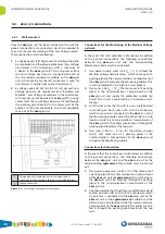
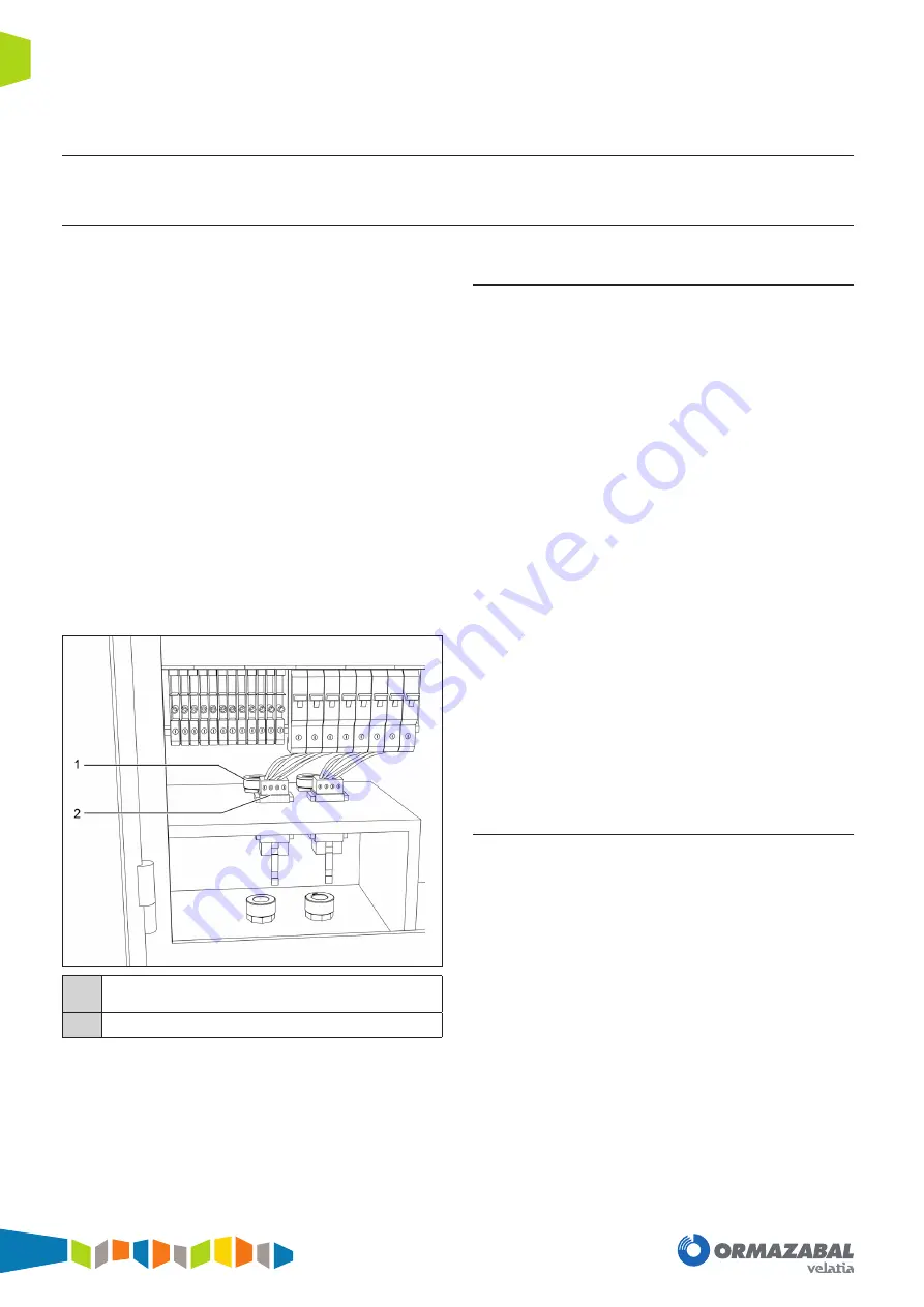
1
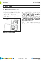
Packing gland for feedthrough of current signals and its
connection to disconnectable and short-circuitable terminals
2
Voltage connectors
Figure 6.3.
Low Voltage Compartment connections
Connections for the Monitoring of the Medium Voltage
network
In the event that the Substation is Monitored, in addition
to the general connections, the following connections
between the ekor.gid unit and the corresponding
Monitoring cubicle must be carried out:
1. Two power supply wires (+48 V
DC
/ 0 V) to feed the
Medium Voltage network relays, which come out of a
packing gland in the Communications Compartment of
the ekor.gid unit and go to the Monitoring cubicle. This
circuit is protected by a miniature circuit-breaker.
2. Two wires (+48 V
DC
/ 0 V
DC
) that come out of a packing
gland in the Communications Compartment of the
ekor.gid unit and supply the protection cubicle trip
circuit. This circuit is protected by a miniature circuit-
breaker.
3. An Ethernet cable sheath with 8 wires, prefabricated
and ending on both sides with an RJ-45 connector,
which on one side is connected to the ekor.rci unit of
the Monitoring cubicle and on the other side to a hub
located inside the Communications Compartment of
the ekor.gid unit. The cables are also fed in through the
packing gland located at the top part.
4. Two wires (+48 V
DC
/ O V
DC
) for the battery charger
alarms that come out of a packing gland in the
Communications Compartment of the ekor.gid unit
and go to the Monitoring cubicle.
Connections for Automation
In the event that the Substation is Automated, in addition
to the general connections, the following connections
between the ekor.gid unit and the ekor.uct unit or the
corresponding cgmcosmos-2lpt cubicle must be carried
out:
1. Two power supply wires (+48 V
DC
/ 0 V) that come out of
a packing gland in the Communications Compartment
of the ekor.uct unit or cgmcosmos-2lpt unit and go to
the ekor.gid unit, also entering through the packing
gland in the Communications Compartment of the
ekor.gid unit.
2. An Ethernet cable sheath with 8 wires, prefabricated and
ending on both sides with an RJ-45 connector, which
on one side is connected to the ekor.ccp unit of the
ekor.uct unit or the cgmcosmos-2lpt cubicle and the
other side to a hub located inside the Communications
Compartment of the ekor.gid unit. The cables are also
fed in through the packing gland located at the top
part.
Summary of Contents for velatia ekor.gid
Page 31: ......

