12 Specifications
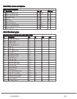
12.3 Lubrication system beka-max
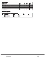
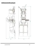
12.6.3 Dimensional sketch F25, operating mode
12.6.4 Dimensional sketch F25, transport mode
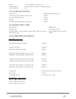
12.1 ELECTRICAL SYSTEM
Power supply:
24 Vdc with alternator located by the pump unit and dual 12 V 55 Ah
lead acid batteries in series.
Sensors:
Position detected
Inductive
Fuchs NBB8-18GM50-E2-V1
Feed hopper:
Ultrasonic, analogue
Fuchs UC2000-30GM70-IE2R2-V15
Wrapping table:
Ultrasonic, digital (70 cm def.)
Microsonic mic+130/D/TC
Oil temperature:
PT1000
FuehlerSysteme EF5/E-20/5
Oil level:
Photoelectric lever
Carlo Gavazzi VP04EP
Chamber pressure:
Pressure, 0-600 bar
IFM PT5460
Elevator pressure:
Pressure 0-250 bar
IFM PT5401
12.2 POWER TAKE OFF
Maximum torque: 2900 Nm
Speed:
850 RPM
12.3 LUBRICATION SYSTEM BEKA-MAX
Grease system:
Voltage
24 Vdc
Maximum current
1,1 A
Pump capacity each revolution
Pump 1 (fixed amount) 0,17 cm³
Pump 2 (adjustable) 0,04 - 0,12 cm³
Pump capacity each minute
4,3 cm³/minute
Maximum pressure
280 bar
Grease type
EP 2 NLGI-2
Volume reservoir
4,0 l
Chain lubrication:
12 SPECIFICATIONS
135
Summary of Contents for Dens-X Compactor
Page 14: ...1 6 DECLARATION OF CONFORMITY 1 GENERAL 14...
Page 103: ...8 7 MANUAL LUBRICATION CHARTS 8 7 1 The compactor 8 LUBRICATION 103...
Page 104: ...8 7 2 Feed hopper F25 8 LUBRICATION 104...
Page 105: ...8 7 3 Flexible drawbar 8 LUBRICATION 105...
Page 109: ...10 1 MAIN POWER SUPPLY E STOP SWITCHES AND ELECTRICAL CABINET 10 ELECTRICS 109...
Page 110: ...10 2 ELECTRICAL CABINET POWER SUPPLY RAIL 10 ELECTRICS 110...
Page 111: ...10 3 SENSORS AND MANUAL CONTROLS 10 ELECTRICS 111...
Page 112: ...10 4 VALVES FAN MOTORS AND PUMPS 10 ELECTRICS 112...
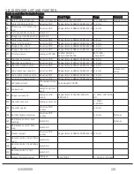
Page 124: ...10 9 SENSOR OVERVIEW 10 ELECTRICS 124...
Page 128: ...11 1 1 Complete diagram 11 HYDRAULICS 128...
Page 129: ...11 1 2 Wrapping table chamber and elevator control 11 HYDRAULICS 129...
Page 130: ...11 1 3 Plastic tying unit sub conveyor and feed hopper 11 HYDRAULICS 130...
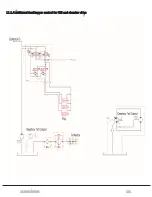
Page 131: ...11 1 4 Additional feed hopper control for F25 and chamber drive 11 HYDRAULICS 131...
Page 133: ...11 2 VALVE OVERVIEW 11 2 1 Valve chart for Dens X 11 HYDRAULICS 133...
Page 137: ...12 6 3 Dimensional sketch F25 operating mode 12 SPECIFICATIONS 137...
Page 138: ...12 6 4 Dimensional sketch F25 transport mode 12 SPECIFICATIONS 138...
Page 142: ...M Maintenance 13 69 71 INDEX 142...

