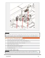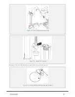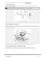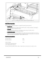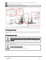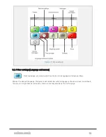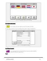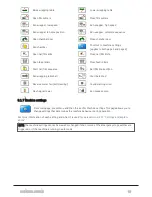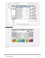
Figure 4.9 :
Compressed air cleaner system on the plastic tying unit
4.10.1 Mode of operation
The three different cleaning processes are triggered by specific signal sequences.
1. Chamber door
Cleans the chamber door contact surfaces when the bale is transported towards the wrapping
table. Triggered by running sub-conveyer.
2. Feed roller
Keeps the feed rollers and their surrounding environment clean from dust and dirt.
Triggered by feed rollers moving to open position.
3. Feed roller slide shafts
Cleans the feed rollers slide shafts located on the plastic tying unit. This enables the wide film to
spread over the entire bale width without any obstructions from the feed rollers due to dirty slide
shafts. Triggered by wrapping table in upper and lower position.
4.10.2 Recommendations
Minimum pressure:
8 bar
Maximum pressure:
12 bar
Number of valves:
3 pcs.
All valves with accompanying filters.
Filter changed when/if necessary.
The valves are located behind the film roller storage. Filters are mounted on the valves rear side.
4 OPERATION
49
Summary of Contents for Dens-X Compactor
Page 14: ...1 6 DECLARATION OF CONFORMITY 1 GENERAL 14...
Page 103: ...8 7 MANUAL LUBRICATION CHARTS 8 7 1 The compactor 8 LUBRICATION 103...
Page 104: ...8 7 2 Feed hopper F25 8 LUBRICATION 104...
Page 105: ...8 7 3 Flexible drawbar 8 LUBRICATION 105...
Page 109: ...10 1 MAIN POWER SUPPLY E STOP SWITCHES AND ELECTRICAL CABINET 10 ELECTRICS 109...
Page 110: ...10 2 ELECTRICAL CABINET POWER SUPPLY RAIL 10 ELECTRICS 110...
Page 111: ...10 3 SENSORS AND MANUAL CONTROLS 10 ELECTRICS 111...
Page 112: ...10 4 VALVES FAN MOTORS AND PUMPS 10 ELECTRICS 112...
Page 124: ...10 9 SENSOR OVERVIEW 10 ELECTRICS 124...
Page 128: ...11 1 1 Complete diagram 11 HYDRAULICS 128...
Page 129: ...11 1 2 Wrapping table chamber and elevator control 11 HYDRAULICS 129...
Page 130: ...11 1 3 Plastic tying unit sub conveyor and feed hopper 11 HYDRAULICS 130...
Page 131: ...11 1 4 Additional feed hopper control for F25 and chamber drive 11 HYDRAULICS 131...
Page 133: ...11 2 VALVE OVERVIEW 11 2 1 Valve chart for Dens X 11 HYDRAULICS 133...
Page 137: ...12 6 3 Dimensional sketch F25 operating mode 12 SPECIFICATIONS 137...
Page 138: ...12 6 4 Dimensional sketch F25 transport mode 12 SPECIFICATIONS 138...
Page 142: ...M Maintenance 13 69 71 INDEX 142...


